STM32 Timer Features
1) The timer can count the input clock and trigger an interrupt when the count value reaches the set value.
2) The time base unit of 16-bit counter, prescaler and automatic reloading register can realize the maximum timing of 59.65s by the 72M counting clock.
a. 16-bit up, down, up/down (center-aligned) counting mode, support automatic reload
b.16-bit prescaler
c. Each timer has multiple independent channels, and each channel can be used for:
* Input capture
* Output compare
* PWM output
* Single pulse mode
d. Advanced timers can also generate complementary outputs.
e. Interrupt/DMA requests can be generated:
* Update events: counter overflow/underflow, counter initialization (via software or internal/external trigger)
* Trigger event: counter starts, stops, initializes or counts with internal/external trigger
* Input capture
* Output compare
f. Timer Counting Mode
Count up mode
The counter counts up (increments) from 0 to the autoload value, then counts back to 0 again and generates a counting overflow event
Count down mode
The counter counts down (decrements) from the autoload value to 0, then back to the autoload value to start counting again, and generates a counting underflow event.
Center-aligned mode (count up/down)
The counter starts counting from 0 to the autoload value -1, generates a counting overflow event, then counts down to 0+1, generates another overflow event, and then counts up.
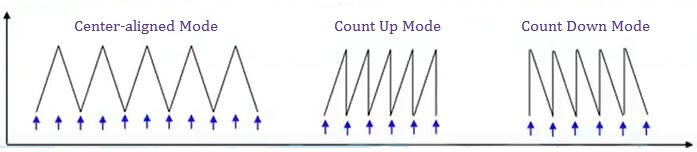
Figure 1: Timer Counting Modes
3) Not only has the basic timer interrupt function, but also includes internal and external clock source selection, input capture, output compare, encoder interface, master-slave trigger mode and other functions.
4) According to the complexity and applications, it is divided into three types: advanced timer, general timer and basic timer.
5) Counting 72 numbers for 72MHz is 1MHz, that is, the time of 1us, and counting 72000 numbers, that is 1KHz, and the time of 1ms.
6) 59.65s =65536 X 65536X 1/72M/(reciprocal of interrupt frequency)
7) The timer of STM32 supports cascading mode: the output of one timer is used as the input of another timer. The maximum timing is 59.65s X 65536 X 65536.
Table 1: Timer Types
|
Type
|
Number
|
Bus
|
Function
|
|
Advanced Timer
|
TIM1、TIM8
|
APB2
|
It has all the functions of a general timer, and additional functions such as repetition counter, dead zone generation, complementary output, brake input, etc.
|
|
General Timer
|
TIM2、TIM3、TIM4、TIM5
|
APB1
|
It has all the functions of the basic timer, and has additional functions such as internal and external clock source selection, input capture, output compare, encoder interface, master-slave trigger mode, etc.
|
|
Basic Timer
|
TIM6、TIM7
|
APB1
|
It has the functions of timing interrupt and master mode triggering DAC.
|
|
*STM32F103C8T6 Timer:TIM1、TIM2、TIM3、TIM4
|
8) Prescaler (PSC): perform a frequency division operation on the input reference frequency in advance.
9) The actual frequency division factor = the value of the prescaler + 1, the maximum can be written 65535 or 65536 frequency division.
10) Counter (CNT): It is also 16 bits, and the value can range from 0 to 65535. When the value of the counter increases (decreases) to the target value, an interrupt is generated to complete the timing.
11) Automatic reload register (): It is also 16 bits. When the count value is equal to the automatic reload value, it means that the timing stops, an interrupt signal will be generated, and the counter will be cleared, and automatically start the next counting time. The interrupt whose value is equal to the auto-reload value is generally called "update interrupt", which will lead to the NVIC. After configuring the timer channel of the NVIC, the update interrupt on the timer will get a response from the CPU. The corresponding event called "update event", it will not trigger an interrupt, but it can trigger the work of other internal circuits.
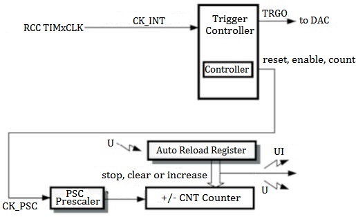
Figure 2: Basic Timer Diagram
12) From the reference clock, to the prescaler, and then to the counter, which is self-incrementing, and at the same time it is constantly compared with the auto-reload register. When the values of the counter and the auto-reload register are equal, that is, the timing stops. An update interrupt and an update event are generated, and the CPU responds to the interrupt, so the timing interrupt is completed.
Master-Slave Trigger Mode
Using the master mode of the timer, the update event of the timer can be mapped to the position of the trigger output TRGO (Trigger Out), and TRGO is directly connected to the trigger conversion pin of the DAC, so the timer does not need to interrupt to trigger the DAC conversion.
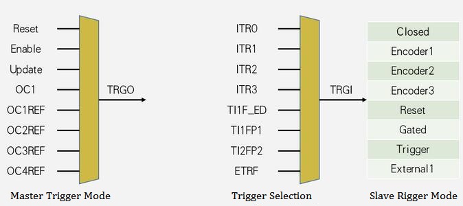
Figure 3: Master Trigger Mode, Slave Trigger Mode, Trigger Selection
Master mode: Map the signal inside the timer to the TRGO pin to trigger other peripherals.
Slave mode: Receive some signals from other peripherals or its own peripherals to control the operation of its own timer, that is, it is controlled by other signals.
Trigger source selection: Select the trigger signal source for the slave mode, which can also be considered as a part of the slave mode. That is, select a specified signal to get TRGI, and TRGI to trigger the slave mode. The slave mode can be selected from the above diagram list. So select one to execute automatically.
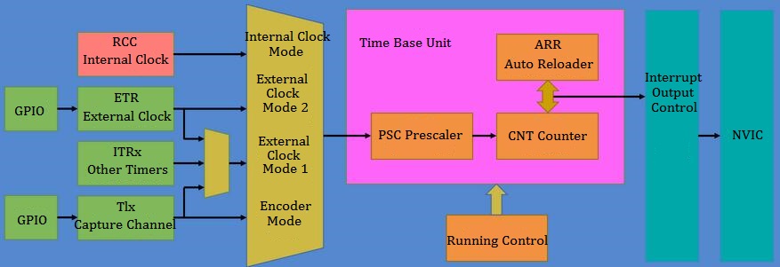
Figure 4: Basic Structure of Timing Interrupt
Buffer register: Change the prescaler from 0 to 1 at a certain moment, and change the frequency division value when the count reaches half. This change will not take effect immediately, but will wait until the end of the counting cycle to generate an update event, so the value of the prescaler will be transferred to the buffer register and take effect.
For example, if we want to change the value in the ARR register, but the current timing has not ended, if the shadow register is not set at this time, the set value will take effect immediately. And if set, the new value will take effect after the end of the current count cycle.
Counter counting frequency: CK_CNT = CK_PSC / (PSC + 1)
Counter overflow frequency: CK_CNT_OV = CK_CNT / (ARR + 1) = CK_PSC / (PSC + 1) / (ARR + 1)
Start Timer Steps
Step 1: RCC turns on the clock.
Step 2: Select the clock source of the time base unit.
Step 3: Configure the time base unit.
Step 4: Configure the output interrupt control to allow the update interrupt output to the NVIC
Step 5: Configure the NVIC, open the timer interrupt channel in the NVIC, and assign a priority
Step 6: Running control
Step 7: Enable counter
Timer Common Library Functions
1) Restore the default configuration function
void TIM_DeInit(TIM_TypeDef* TIMx);
2) Time base unit initialization function
void TIM_TimeBaseInit(TIM_TypeDef* TIMx, TIM_TimeBaseInitTypeDef* TIM_TimeBaseInitStruct);
3) Assign the structure variable a default value function
void TIM_TimeBaseStructInit(TIM_TimeBaseInitTypeDef* TIM_TimeBaseInitStruct);
4) Enable counter function
void TIM_Cmd(TIM_TypeDef* TIMx, FunctionalState NewState);
5) Enable interrupt output signal function
void TIM_ITConfig(TIM_TypeDef* TIMx, uint16_t TIM_IT, FunctionalState NewState);
6) Select the internal clock function
void TIM_InternalClockConfig(TIM_TypeDef* TIMx);
7) Select the clock function of other timers of ITRx
void TIM_ITRxExternalClockConfig(TIM_TypeDef* TIMx, uint16_t TIM_InputTriggerSource);
8) Select the clock function of the TIx capture channel
void TIM_TIxExternalClockConfig(TIM_TypeDef* TIMx, uint16_t TIM_TIxExternalCLKSource,uint16_t TIM_ICPolarity, uint16_t ICFilter);
Parameter 3: Polarity of input Parameter 4: Filter
9) Select the clock function input by ETR through external clock mode 1
void TIM_ETRClockMode1Config(TIM_TypeDef* TIMx, uint16_t TIM_ExtTRGPrescaler, uint16_t TIM_ExtTRGPolarity, uint16_t ExtTRGFilter);
Parameter 2: Prescaler Parameter 3: Input Polarity Parameter 4: Filter
10) Select the clock function input by ETR through external clock mode 2
void TIM_ETRClockMode2Config(TIM_TypeDef* TIMx, uint16_t TIM_ExtTRGPrescaler, uint16_t TIM_ExtTRGPolarity, uint16_t ExtTRGFilter);
11) Separately configure the functions of the prescaler, polarity, and filter parameters of the ETR pin
void TIM_ETRConfig(TIM_TypeDef* TIMx, uint16_t TIM_ExtTRGPrescaler, uint16_t TIM_ExtTRGPolarity, uint16_t ExtTRGFilter);
12) Write prescaler value function separately
void TIM_PrescalerConfig(TIM_TypeDef* TIMx, uint16_t Prescaler, uint16_t TIM_PSCReloadMode);
Parameter 3: As for the writing mode, when the update event takes effect, or after writing, manually generate an update event to make this value take effect immediately.
13) Change the counting mode function
void TIM_CounterModeConfig(TIM_TypeDef* TIMx, uint16_t TIM_CounterMode);
14) Automatic reloader pre-installation configuration function
TIM_ARRP reload Config is set to DISABLE and ENABLE, its function is only to allow or prohibit writing new values to the ARR buffer when the timer is working, so that when an update event occurs, the previous value is loaded and overwritten.
void TIM_ARRPreloadConfig(TIM_TypeDef* TIMx, FunctionalState NewState);
15) Write a value function to the counter
void TIM_SetCounter(TIM_TypeDef* TIMx, uint16_t Counter);
16) Write a value function to the auto-reloader
void TIM_SetAutoreload(TIM_TypeDef* TIMx, uint16_t Autoreload);
17) Get the value function of the current counter
uint16_t TIM_GetCounter(TIM_TypeDef* TIMx);
18) Get the value function of the current prescaler
uint16_t TIM_GetPrescaler(TIM_TypeDef* TIMx);
Use cross-file variables: extern declares variables to tell the compiler that the variable Num is defined in other files and can also be used in this file.
* Programming Example
void Timer_Init(void)
{
RCC_APB1PeriphClockCmd(RCC_APB1Periph_TIM2, ENABLE);//turn on the TIM2 clock
TIM_InternalClockConfig(TIM2);//use internal clock
TIM_TimeBaseInitTypeDef TIM_TimeBaseInitStructure;//define the time base unit structure
TIM_TimeBaseInitStructure.TIM_ClockDivision = TIM_CKD_DIV1;//set no frequency division
TIM_TimeBaseInitStructure.TIM_CounterMode = TIM_CounterMode_Up;//set count up
TIM_TimeBaseInitStructure.TIM_Period = 10000 - 1;//ARR auto-reload value
TIM_TimeBaseInitStructure.TIM_Prescaler = 7200 - 1;//PSC does not divide frequency
TIM_TimeBaseInitStructure.TIM_RepetitionCounter = 0;//repeat counter value, specific to advanced timers
TIM_TimeBaseInit(TIM2, &TIM_TimeBaseInitStructure);//write parameter
TIM_ClearFlag(TIM2, TIM_FLAG_Update);//clear update flag
TIM_ITConfig(TIM2, TIM_IT_Update, ENABLE);//interrupt output
NVIC_PriorityGroupConfig(NVIC_PriorityGroup_2);//interrupt priority grouping
NVIC_InitTypeDef NVIC_InitStructure;//NVIC structure
NVIC_InitStructure.NVIC_IRQChannel = TIM2_IRQn;//timer channel
NVIC_InitStructure.NVIC_IRQChannelCmd = ENABLE;//enable
NVIC_InitStructure.NVIC_IRQChannelPreemptionPriority = 2;//preemptive priority
NVIC_InitStructure.NVIC_IRQChannelSubPriority = 1;//response priority
NVIC_Init(&NVIC_InitStructure);//write parameter
TIM_Cmd(TIM2, ENABLE);//enable timer
}
/*
void TIM2_IRQHandler(void)
{
if (TIM_GetITStatus(TIM2, TIM_IT_Update) == SET)//determine whether the interrupt overflow
{
TIM_ClearITPendingBit(TIM2, TIM_IT_Update);//clear interrupt flag
}
}
*/
Output Compare (OC)
1) The output compare can set the output level to 1, 0 or reverse the operation by comparing the relationship between the CNT and CCR register values, which is used to output PWM waveforms with a certain frequency and duty cycle.
2) Each advanced timer and general purpose timer has 4 output compare channels.
3) The first 3 channels of the advanced timer additionally have the function of dead generation and complementary output.
Common OC Functions
Configure the OC function
void TIM_OC1Init(TIM_TypeDef* TIMx, TIM_OCInitTypeDef* TIM_OCInitStruct);
void TIM_OC2Init(TIM_TypeDef* TIMx, TIM_OCInitTypeDef* TIM_OCInitStruct);
void TIM_OC3Init(TIM_TypeDef* TIMx, TIM_OCInitTypeDef* TIM_OCInitStruct);
void TIM_OC4Init(TIM_TypeDef* TIMx, TIM_OCInitTypeDef* TIM_OCInitStruct);
Assign a default value function to the OC structure
void TIM_OCStructInit(TIM_OCInitTypeDef* TIM_OCInitStruct);
Configure the forced output mode function
If you want to suspend the output waveform and force the output to be high or low during operation, forcing the output to be high is the same as setting a 100% duty cycle, and forcing the output to be low is the same as setting a 100% low level.
void TIM_ForcedOC1Config(TIM_TypeDef* TIMx, uint16_t TIM_ForcedAction);
void TIM_ForcedOC2Config(TIM_TypeDef* TIMx, uint16_t TIM_ForcedAction);
void TIM_ForcedOC3Config(TIM_TypeDef* TIMx, uint16_t TIM_ForcedAction);
void TIM_ForcedOC4Config(TIM_TypeDef* TIMx, uint16_t TIM_ForcedAction);
Configure the pre-installed function of the CCR register
The pre-installed function is a shadow register: the written value will not take effect immediately, but will take effect only after the update event.
void TIM_OC1PreloadConfig(TIM_TypeDef* TIMx, uint16_t TIM_OCPreload);
void TIM_OC2PreloadConfig(TIM_TypeDef* TIMx, uint16_t TIM_OCPreload);
void TIM_OC3PreloadConfig(TIM_TypeDef* TIMx, uint16_t TIM_OCPreload);
void TIM_OC4PreloadConfig(TIM_TypeDef* TIMx, uint16_t TIM_OCPreload);
Configure the quick enable function
void TIM_OC1FastConfig(TIM_TypeDef* TIMx, uint16_t TIM_OCFast);
void TIM_OC2FastConfig(TIM_TypeDef* TIMx, uint16_t TIM_OCFast);
void TIM_OC3FastConfig(TIM_TypeDef* TIMx, uint16_t TIM_OCFast);
void TIM_OC4FastConfig(TIM_TypeDef* TIMx, uint16_t TIM_OCFast);
Clear REF signal function when having external event
void TIM_ClearOC1Ref(TIM_TypeDef* TIMx, uint16_t TIM_OCClear);
void TIM_ClearOC2Ref(TIM_TypeDef* TIMx, uint16_t TIM_OCClear);
void TIM_ClearOC3Ref(TIM_TypeDef* TIMx, uint16_t TIM_OCClear);
void TIM_ClearOC4Ref(TIM_TypeDef* TIMx, uint16_t TIM_OCClear);
Sets the polarity function of the output compare independently
The one with N is the configuration function of the complementary channel in the advanced timer.
void TIM_OC1PolarityConfig(TIM_TypeDef* TIMx, uint16_t TIM_OCPolarity);
void TIM_OC1NPolarityConfig(TIM_TypeDef* TIMx, uint16_t TIM_OCNPolarity);
void TIM_OC2PolarityConfig(TIM_TypeDef* TIMx, uint16_t TIM_OCPolarity);
void TIM_OC2NPolarityConfig(TIM_TypeDef* TIMx, uint16_t TIM_OCNPolarity);
void TIM_OC3PolarityConfig(TIM_TypeDef* TIMx, uint16_t TIM_OCPolarity);
void TIM_OC3NPolarityConfig(TIM_TypeDef* TIMx, uint16_t TIM_OCNPolarity);
void TIM_OC4PolarityConfig(TIM_TypeDef* TIMx, uint16_t TIM_OCPolarity);
Modify the output enable parameter function separately
void TIM_CCxCmd(TIM_TypeDef* TIMx, uint16_t TIM_Channel, uint16_t TIM_CCx);
void TIM_CCxNCmd(TIM_TypeDef* TIMx, uint16_t TIM_Channel, uint16_t TIM_CCxN);
Select output compare mode function
void TIM_SelectOCxM(TIM_TypeDef* TIMx, uint16_t TIM_Channel, uint16_t TIM_OCMode);
Functions that individually change the value of the CCR register
void TIM_SetCompare1(TIM_TypeDef* TIMx, uint16_t Compare1);
void TIM_SetCompare2(TIM_TypeDef* TIMx, uint16_t Compare2);
void TIM_SetCompare3(TIM_TypeDef* TIMx, uint16_t Compare3);
void TIM_SetCompare4(TIM_TypeDef* TIMx, uint16_t Compare4);
Call the enable main output function when using advanced timer output PWM
void TIM_CtrlPWMOutputs(TIM_TypeDef* TIMx, FunctionalState NewState);
The timer output needs to use the multiplexed push-pull output, and the control of the multiplexed push-pull output pin can be handed over to the on-chip peripherals, and the PWM waveform can be output through the pin.
Pin Remapping
Enable AFIO clock function
void GPIO_PinRemapConfig(uint32_t GPIO_Remap, FunctionalState NewState);
Complete remapping: all four pins changed
Partial remapping: the first two pins changed or the last two pins changed.
The debug port cannot be used as a normal GPIO port, and it needs to be demultiplexed
* Programming Example
void PWM_Init(void)
{
RCC_APB1PeriphClockCmd(RCC_APB1Periph_TIM2, ENABLE);//turn on the TIM2 clock
RCC_APB2PeriphClockCmd(RCC_APB2Periph_GPIOA, ENABLE);//turn on the GPIO clock
GPIO_InitTypeDef GPIO_InitStructure;//define the GPIO structure
GPIO_InitStructure.GPIO_Mode = GPIO_Mode_AF_PP;//multiplexed push-pull output
GPIO_InitStructure.GPIO_Pin = GPIO_Pin_2;//enable pin
GPIO_InitStructure.GPIO_Speed = GPIO_Speed_50MHz;//configure response speed
GPIO_Init(GPIOA, &GPIO_InitStructure);//write parameter
TIM_InternalClockConfig(TIM2);//use internal clock
TIM_TimeBaseInitTypeDef TIM_TimeBaseInitStructure;//configure time base unit
TIM_TimeBaseInitStructure.TIM_ClockDivision = TIM_CKD_DIV1;//no frequency division
TIM_TimeBaseInitStructure.TIM_CounterMode = TIM_CounterMode_Up;//count up
TIM_TimeBaseInitStructure.TIM_Period = 100 - 1; //ARR
TIM_TimeBaseInitStructure.TIM_Prescaler = 36 - 1; //PSC
TIM_TimeBaseInitStructure.TIM_RepetitionCounter = 0;//repeat counter
TIM_TimeBaseInit(TIM2, &TIM_TimeBaseInitStructure);//write parameter
TIM_OCInitTypeDef TIM_OCInitStructure;//define the output compare structure
TIM_OCStructInit(&TIM_OCInitStructure);//set default values to the structure
TIM_OCInitStructure.TIM_OCMode = TIM_OCMode_PWM1;//PWM1 model
TIM_OCInitStructure.TIM_OCPolarity = TIM_OCPolarity_High;//active level is high
TIM_OCInitStructure.TIM_OutputState = TIM_OutputState_Enable;//enable
TIM_OCInitStructure.TIM_Pulse = 0; //CCR
TIM_OC3Init(TIM2, &TIM_OCInitStructure);//write parameter
TIM_Cmd(TIM2, ENABLE);//enable clock
}
void PWM_SetCompare3(uint16_t Compare)
{
TIM_SetCompare3(TIM2, Compare);//set the value of CCR3
}
Input Capture (IC)
A Short Brief
In input capture mode, when the channel input pin has a specified level transition, the current CNT value will be latched into the CCR, which can be used to measure the frequency, duty cycle, pulse interval, level duration, etc. of the PWM waveform.
Each advanced timer and general timer has 4 input capture channels.
Configure PWMI mode to measure frequency and duty cycle simultaneously.
It can cooperate with the master-slave trigger mode to realize the hardware automatic measurement.
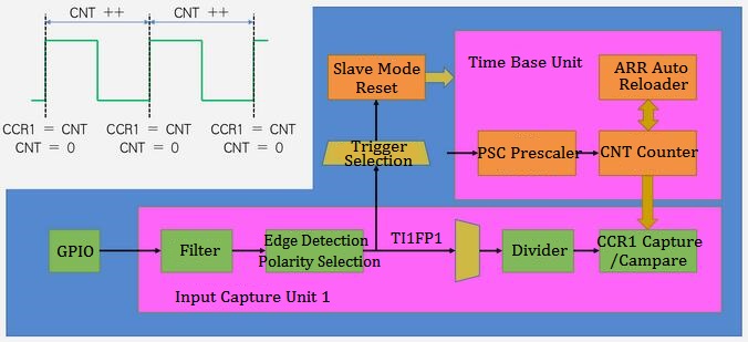
Figure 5: Input Capture Basic Structure
* Programming Example
RCC_APB1PeriphClockCmd(RCC_APB1Periph_TIM3, ENABLE);
RCC_APB2PeriphClockCmd(RCC_APB2Periph_GPIOA, ENABLE);
GPIO_InitTypeDef GPIO_InitStructure;
GPIO_InitStructure.GPIO_Mode = GPIO_Mode_IPU;
GPIO_InitStructure.GPIO_Pin = GPIO_Pin_6;
GPIO_InitStructure.GPIO_Speed = GPIO_Speed_50MHz;
GPIO_Init(GPIOA, &GPIO_InitStructure);
TIM_InternalClockConfig(TIM3);
TIM_TimeBaseInitTypeDef TIM_TimeBaseInitStructure;
TIM_TimeBaseInitStructure.TIM_ClockDivision = TIM_CKD_DIV1;
TIM_TimeBaseInitStructure.TIM_CounterMode = TIM_CounterMode_Up;
TIM_TimeBaseInitStructure.TIM_Period = 65536 - 1; //ARR
TIM_TimeBaseInitStructure.TIM_Prescaler = 72 - 1; //PSC
TIM_TimeBaseInitStructure.TIM_RepetitionCounter = 0;
TIM_TimeBaseInit(TIM3, &TIM_TimeBaseInitStructure);
TIM_ICInitTypeDef TIM_ICInitStructure;//define input capture structure
TIM_ICInitStructure.TIM_Channel = TIM_Channel_1;//channel 1
TIM_ICInitStructure.TIM_ICFilter = 0xF;//filter open max
TIM_ICInitStructure.TIM_ICPolarity = TIM_ICPolarity_Rising;//rising edge trigger
TIM_ICInitStructure.TIM_ICPrescaler = TIM_ICPSC_DIV1;//no frequency division
TIM_ICInitStructure.TIM_ICSelection = TIM_ICSelection_DirectTI;//direct mode
TIM_ICInit(TIM3, &TIM_ICInitStructure);
TIM_SelectInputTrigger(TIM3, TIM_TS_TI1FP1);//select trigger source
TIM_SelectSlaveMode(TIM3, TIM_SlaveMode_Reset);//slave mode
TIM_Cmd(TIM3, ENABLE);//enable timer
}
uint32_t IC_GetFreq(void)
{
return 1000000 / (TIM_GetCapture1(TIM3) + 1);
}

 English