If you are an iphone user, you must know the Airdrop of iphone11. How is this function realized? Because it uses the ultra wide-band UWB chip, the so-called U1, to realize space perception, that is, through positioning technology. Then Samsung, Xiaomi and other companies successively adopted UWB technology in their mobile phones, which made the long-silent UWB technology become popular again in the past two years. So what is UWB?
Ultra-Wideband (UWB) Basic
Ultra-Wideband (UWB) is a wireless communication technology using a frequency bandwidth above 1GHz. Different from traditional narrowband communication technology, UWB realizes wireless transmission by sending and receiving non-sinusoidal extremely narrow pulses with nanosecond or microsecond level, which can realize the application of ultra-wideband spectrum (above 500MHz). Although wireless communication is used, its data transfer rate can reach more than a few hundred megabits per second. Actually, UWB is not a new technology, it has been existed since the 1960s. It is mainly used in the military field, and it was not used in the civilian field until 2002. Why did everyone feel unfamiliar with it for such a long time? Because, at that time, the UWB ecosystem was incomplete and the cost was high. Also under the double attack of USB and Wi-Fi, the development space was limited.
With the development of technology, UWB has been valued because it can provide more accurate directions, and can use high-precision timing for distance measurement, so it is finally found in the civilian field by indoor positioning. Then the question comes, there are many indoor positioning technologies, such as Bluetooth, Wi-Fi, etc., why choose UWB technology?
First of all, the traditional global navigation satellite system (GNSS) can provide satellite positioning services, but its signals will be blocked by buildings to achieve indoor positioning. Wi-Fi and Bluetooth typically use received signal strength indicators (RSSI) to determine location, showing only a rough classification of "weak" or "strong" received signals, with accuracy up to the meter level. This is not enough to meet our needs.
There are three technologies for UWB positioning, namely TOF (time of flight), TDOA (time difference of arrival) and PDOA (phase difference of arrival). While this only works at short ranges, it can determine the location of a signal source with accuracy less than 50cm (under optimal conditions and deployments) and extremely low latency.
UWB for Indoor Positioning
UWB can achieve more accurate indoor positioning and distance measurement than other technologies. As shown in the figure below, UWB pulses (middle and right plots) are only 2 nanoseconds (ns) wide and don’t affected by reflected signal (multipath) interference and noise. UWB radio frequency pulses have sharp edges, allowing precise time-of-arrival and distance determinations in the presence of signal reflections and common multipath effects.
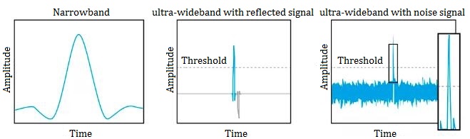
Figure 1: Comparing Narrowband Signal Impulse Radio with Direct and Reflected Signal
When using UWB, the reflected signal doesn’t affect the direct signal. The IR-UWB signal (middle and right) has shorter rise and fall times (edges) than a standard narrowband signal (left), so the signal's arrival time can be accurately measured. This also helps UWB signals maintain their integrity and structure in the case of noise and multipath effects. For example, as shown in Figure 1, the arrival time of 2ns UWB pulses is barely affected. In contrast, narrowband signals are significantly affected by noise as shown in the figure below.
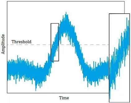
Figure 2: Narrowband with Noise
We have experimented with ToF-based methods using narrowband radio technology. As shown in Figure 3, narrowband signals are very sensitive to multipath because the reflected signal (dark gray) can destructively combine with the direct warp signal (light gray) to generate the final signal at the receiver (blue). This affects the signal crosses the threshold (used to measure ToA), reducing accuracy.
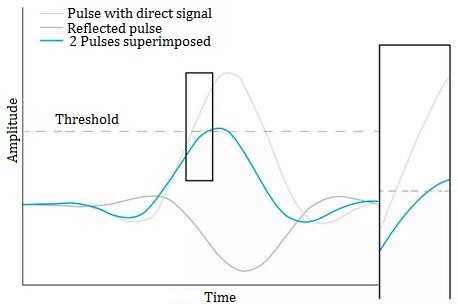
Figure 3: Narrowband with Reflections
This shows that UWB has the following characteristics:
1) Ultra-accurate: providing centimeter-level accuracy, 100 times more accurate than BLE and Wi-Fi.
2) Ultra-reliable: maintaining signal integrity in the presence of multipath reflections.
3) Real-time: with 50 times lower latency than global positioning system (GPS) and 3,000 times lower than standard beacons.
Main UWB Indicators
Frequency range: 3.1GHz~10.6GHz
System power consumption: 1mW~4mW
Pulse width: 0.2ns~1.5ns
Repeat cycle: 25ns~1ms
Transmit power: <-41.3 dBm/MHz
Data rate: tens to hundreds of Mb/s
Decomposition multipath delay: ≤1ns
Multipath fading: ≤5dB
System capacity: much higher than 3G system
Space capacity: 1000kb/m2
Slot Time
The time slots of UWB technology are divided into two categories:
Synchronization Time Slot: The synchronization signal uses a fixed time slot, and each carrier receives the signal and synchronizes its phase and amplitude when sending.
Asynchronous Time Slot: Each carrier receives a sinusoidal signal with varying phase and amplitude, demodulates it into a time slice, and then converts it into a time slice again through time-frequency.
Due to the narrow beam and low power, UWB signals are usually used to transmit data when locating targets, instead of using multiple radio frequency antennas to transmit signals, in addition, RF antennas can only be used to receive data. Therefore, when using UWB communication, the problem of transmission power must be considered. Usually, includes several aspects: first, the selection of the transmission time point; second, the receiver needs to be set at the receiving end to identify whether it is from the target position; finally, the type of signal received is used to select the correct beam.
UWB System Considerations
1) Anchor and Tag
To understand UWB systems, you first need to understand anchors and tags. An anchor is usually a fixed UWB device, while tags usually refer to mobile UWB devices. Anchor and tag exchange information to determine the distance between the two. The exact location of a tag can be determined by communicating with multiple anchors. Some devices can act as both anchors and tags. For example, when two mobile phones use UWB to calculate the distance between each other, they can switch roles during the calculation, alternately serving as a tag or an anchor.
2) Storage Units and Processing Power
A typical UWB device requires a certain degree of processing capability and specific functions. For simple tags, the processor is required to have a small amount of flash memory (programmable nonvolatile memory) and data storage (volatile random access memory, or RAM). For anchor applications, such as those used in time difference of arrival (TDoA), processors with more flash memory, RAM, and in many cases data backhaul may be required.
The diagram below shows a common architecture for a tag (with motion detection) or an anchor (with a backhaul interface such as an internet or Wi-Fi interface). For anchors, different types of processors may be required, depending on systems and workload/throughput requirements.
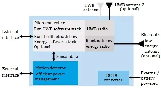
Figure 4: Typical UWB Architecture
3) Antenna
Different applications will require different antennas. For example, tags often use small omnidirectional antennas, while anchor points may use directional antennas, depending on topology.
4) Software Stack
The important interconnection between UWB communication components and applications is the software stack, as shown in the figure. It helps coordinate interoperability and coexistence with external devices. Additionally, software enables communication between the UWB communication components and the internal microcontroller. For example, when controlling a connection between a smartphone and a car, software is responsible for coordinating the communication.
The software can also manage multiple applications and use cases simultaneously. For example, a solution might be part of a smart home ecosystem that controls speakers, lighting, heating, and more. It can communicate with all UWB tags and UWB-enabled devices while utilizing location information to control on and off, or more settings. The UWB software stack can handle all these different situations simultaneously to meet the needs of different applications. In short, using it can make things easier from an end-user and overall system design perspective.
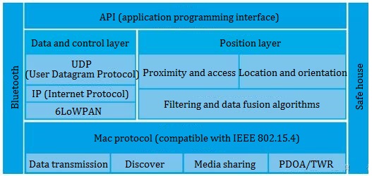
Figure 5: UWB Software Stack
5) Feature Prioritization
Functions in different scenarios need to be prioritized. For example, imagine an application where power management and battery life are more important than location update rate or data throughput. In this case, software can be used to optimize power consumption by setting the device to be off when not in use and on when communication is required.
Another situation is that the sensor LOS signal is not ideal or coming from a different direction. At this point, software can be used to average the results to obtain accurate distance information, and it can also smooth signals that are noisier than others. For more accurate results, especially in fast-moving applications, or to add information about the orientation of the device, the software can also combine data from the UWB chipset and data from inertial measurement devices (including accelerometer, gyroscope, magnetometer, etc.).
UWB Topology Comparison
Comparison Under Different Conditions
UWB utilizes the concept of ToF, a method of measuring the distance between two radio transceivers by multiplying the ToF of a signal by the speed of light. Based on this basic principle, UWB technology can be implemented in different ways according to the needs of the target application.
The optimal topology is mainly determined by the application. That is to say, the design engineer must first match the application and the topology. The available methods are:
Two-way ranging (TWR): As shown in the figure below, the TWR method calculates the distance between the tag and the anchor by measuring the ToF of the UWB RF signal and then multiplying this time by the speed of light. For example, an automotive keyless entry system is an application using the TWR, which generates a secure space, similar to a security bubble, while ensuring that the bubble maintains high-precision security control when applied.
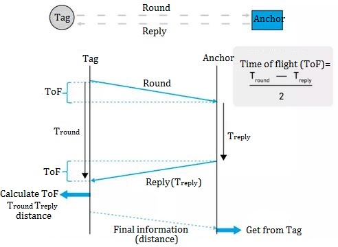
Figure 6: Using Tag and Anchor to Calculate Safe Distance
If you implement a TWR scheme between two devices, you can get distance information between the devices. Building on the TWR scheme, you can also achieve 2D or even 3D position measurement between a mobile tag and a fixed anchor point, called "trilateration".
With the TWR method, three messages can be exchanged. Tags initiate TWR by sending a poll message with a known anchor address. The anchor records the time the poll was received, and replies with a response message. After receiving the response message, the tag records the time and writes the last message. The anchor can use the information in the last message to determine the ToF of the UWB signal.
The TWR approach can also be used in the 2D/3D asset scenarios shown in Figure 7 and Figure 8. Figure 7 shows TWR using a listener, while Figure 8 shows TWR using a data tag backhaul. As shown in the figure, data backhaul can be achieved using various methods (such as Wi-Fi, NB-IoT, LTE-M, etc.) to transfer the data to the cloud disk.
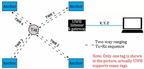
Figure 7: TMR with 2D /3D Asset and Listener
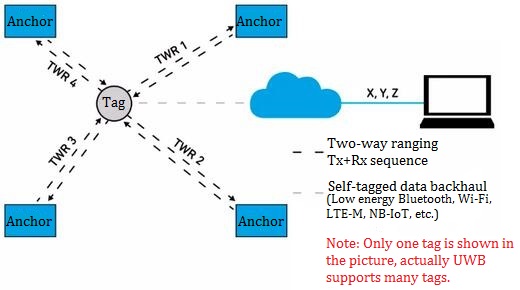
Figure 8: TMR with 2D /3D Asset and Data Tag Backhaul
Time Difference of Arrival (TDoA) and Reverse TDoA: they are similar to GPS. Multiple reference points, called "anchor points", are deployed at known fixed locations and are closely synchronized in time. In the case of TDoA, the mobile device will blink (i.e. periodically send information) and when the beacon signal is received by the anchor, it will be timestamped based on a common synchronized time base. Timestamps from multiple anchors are then forwarded to a central location engine, which runs a multilateration algorithm based on each anchor's beacon signal TDoA. Finally, the 2D or 3D position of the mobile device will be obtained, as shown in Figure 9. Reverse TDoA is more like GPS. In this system, anchors send synchronous beacons (with fixed/known offsets to avoid collisions) and mobiles compute their positions using TDoA and multilateration algorithms, as shown in Figure 10.
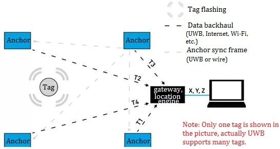
Figure 9: TDoA
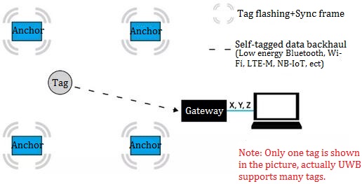
Figure 10: Reverse TDoA
Phase Difference of Arrival (PDoA): Another UWB topology is PDoA. PDoA combines the distance between two devices with a bearing measurement between the two, as shown in the figure. Using the combined distance and bearing information, the relative position of two devices can be calculated without any additional infrastructure. To do this, one of the devices must be equipped with at least 2 antennas and be able to measure the phase difference of the arriving signal carrier at each antenna. The phase is completely unaffected by antenna deformation and enables better than 10° measurement accuracy, allowing transmitter orientation to be determined to less than 5°.
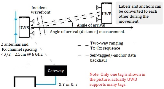
Figure 11: PDoA Positioning and Navigation Service
Which application is best suited for each topology? These use cases mainly focus on three different areas: contactless door access (TWR), location-based services (TDOA), and device-to-device (point-to-point) (PDoA) applications.
UWB Organizations and Standards
Each wireless transmission technology usually has a standard organization responsible for the formulation of relevant standards and technical certification. In the field of UWB technology, it mainly includes IEEE, UWB Alliance and the newly established FiRa Consortium.
The IEEE 802.15.4a standard is the first international standard specifying the wireless physical layer for precise ranging. At present, the IR-UWB channel adopts it, also UWB chips (including DW1000) generally adopt this model.
The FiRa Consortium is committed to developing and broadly adopting interoperable UWB technology to bring secure fine-grained ranging and positioning function to provide users with a seamless experience. It mainly develops products based on IEEE 802.15.4 standard UWB security and fine ranging technology, and develops application scenarios of UWB technology across various vertical business fields. FiRa works closely with other industry groups such as IEEE, Wi-Fi Alliance, Car Connectivity Consortium (CCC), and others, focusing on UWB technology operating in the available 6-9 GHz frequency bands.
The UWB Alliance is focused on providing a favorable regulatory and spectrum management environment under the 802.15.4z standard to expand the UWB market. It aims to demonstrate the value of UWB to the Internet of Things and Industry 4.0 greatly, and build a global ecosystem in the entire UWB chain from chips to services.
UWB Advantages
1) Simple System Structure
UWB technology transmits data signals by sending nanosecond-level non-sinusoidal narrow pulses. The transmitter in the UWB system directly excites the antenna with a small pulse, which does not need the up-conversion required by the traditional transceiver, thus cutting the need for a operational amplifier and a mixer. UWB systems allow the use of very inexpensive broadband transmitters. At the same time, the receiver of the UWB system is also different from the traditional receiver in that it does not require intermediate frequency processing. Therefore, the realization of the UWB system structure is relatively simple.
2) High-speed Data Transmission
UWB technology can exchange high-speed data transmission with a very wide frequency bandwidth, and it does not occupy the already crowded frequency resources, but shares the frequency band used by other wireless technologies. In military applications, UWB technology can use huge spread spectrum gain to achieve long-distance, low interception rate, low detection rate, high security and high-speed data transmission.
3) Low Power Consumption
The UWB system uses intermittent pulses to send data. The pulse duration is very short, generally between 0.20 and 1.5 n, and has very low duty cycle ratio. The power of civilian UWB equipment is generally about 1/100 of the power required by traditional mobile phones, and about 1/20 of the power required by Bluetooth devices, in addition, military UWB radios also consume very little power.
4) High Security
As the physical layer technology of the communication system, UWB technology has natural security performance. Since UWB signals generally disperse signal energy in an extremely wide frequency band, for general communication systems, UWB signals are equivalent to white noise signals, and in most cases, the power spectral density of UWB signals is lower than natural electronic noise power spectral density.
5) Strong Multipath Resolution Ability
Since UWB radios transmit single-cycle pulses with a very short duration and a very small duty cycle, multipath signals are separable in time. If multipath pulses are to overlap in time, the length of the multipath transmission path should be less than the product of pulse width and propagation velocity. Also, the pulse multipath signals do not overlap in time, so it is easy to separate the multipath components to make full use of the energy of the transmitted signal. A large number of experiments have shown that for the multipath environment where the multipath fading of conventional radio signals is as deep as 10~30dB, the fading of UWB radio signals is less than 5dB at most.
6) Precise Positioning
Using UWB technology, it is easy to integrate positioning and communication, which is difficult for conventional radios. UWB technology has extremely strong penetrating ability, and can perform precise positioning indoors and underground, while GPS (global positioning system) can only work within the visible range of positioning satellites. Different from the absolute geographic position provided by GPS, the UWB radio locator can provide relative position, and its positioning accuracy can reach centimeter level.
7) Simple and Low Cost
In terms of engineering realization, UWB technology is much simpler than other wireless technologies and can be fully digitalized. It only needs to generate pulses in a mathematical way and modulate the pulses, and the circuits required to realize the above process can be integrated on a chip, so the cost of the device is very low.

 English










