Controller Area Network (CAN or CAN bus for short) is a decentralized communication protocol. Because it was developed by BOSCH (1) as a multi-master, message broadcast system, and the earliest CAN controlling chip was applied and mass-produced in Mercedes-Benz cars. Because it supports the advantages of multiple hosts and slaves, it only needs two lines for direct communication between all controllers, sensors, and electronic devices in a car, which greatly optimizes the wiring of the entire vehicle. CAN bus uses a form of "twisted pair" distributed among different computers, called "controller area network bus". What 's the specific of CAN bus and what do you need to care?
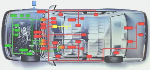
Controller Area Network (CAN)
Working Principle
The CAN bus uses a serial data transmission method, which can run on a 40m twisted pair at a rate of 1Mb/s, or can be connected with an optical cable, and it supports multi-master controllers on this bus. CAN is similar to the I2C bus in many details, but there are some notable differences. When a node on the CAN bus sends data, it is broadcast to all nodes in the network in the form of a message. For each node, no matter the data is sent or not, it will be received. The 11 characters at the beginning of each group of messages are identifiers, which define the priority of the messages. This message format is called a content-oriented addressing. In addition, identifiers are unique within the same system, and it is impossible for two stations to send messages with the same one. So it is important when several stations are competing for bus reads at the same time.
When a station wants to send data to other stations, the CPU of the station transmits the data to be sent and its own identifier to the CAN chip, and is in the ready state; when it receives the bus allocation, it turns to the sending state. The CAN chip organizes the data into a certain message format according to the protocol and sends it out. At this time, other stations on the network are in the receiving state. Each station in the receiving state detects the received messages and judges whether these messages are sent to itself to determine whether to receive it. Since the CAN bus is a content-oriented addressing scheme, it is easy to build a high-level control system and configure it flexibly. For example, we can easily add some new stations in the CAN bus without modifying the hardware or software. When the provided new station is a pure data receiving device, the data transfer protocol does not require the separate part to have a physical destination address, which allows the synchronization of distributed processes, that is, when the controllers on the bus need measurement data, they can be obtained from the network, without the need for each controller to have its own independent sensor.
CAN Standard
|
Standard
|
Description
|
|
ISO 11898-1
|
Data link layer
|
|
ISO 11898-2
|
Physical layer of high-speed CAN
|
|
ISO 11898-3
|
The physical layer of low-speed fault-tolerant CAN
|
What is the physical layer here? In fact, it is the transmission process of the electrical signal of CAN. CAN has only two differential signal lines, CAN_HIGH and CAN_LOW. Data is communicated through differential signals. Its advantage is that it can increase the anti-interference ability of the signal and suppress the interference of common-mode signals.
The details are shown in the figure below:
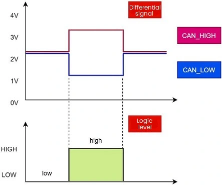
Figure 1: CAN Differential Signal
Therefore, before the signal becomes a byte-by-byte digital signal, it is transmitted according to this differential analog signal. To put it simply, when CAN_HIGH minus CAN_LOW is greater than a certain threshold, it can be regarded as high logic level, otherwise, when it is less than a certain threshold, it becomes low logic level.
Connection
The CAN bus supports multiple nodes to be mounted on the bus, which is similar to the I2C bus, and multiple slaves can be mounted on SCL and SDA, as shown in the following figure:
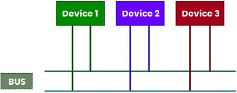
Figure 2: CAN Connection Method
However, the CAN bus does not actually have the concept of master-slave. Each device is a node (Node), and the nodes can communicate with each other directly. Compared with the I2C bus, the CAN bus is equipped with a terminal resistor, which is a common closed-loop connection mode. There is also an open-loop connection mode.
Different connection modes have different communication rates, which is the difference between high-speed CAN and low-speed CAN.
The two wires form a twisted pair and are connected with a characteristic impedance of 120Ω. The highest communication rate of this mode can reach 1Mbps. The following is the transmission relationship between distance and speed:
|
Bus Length (m)
|
Signaling Rate (Mbps)
|
|
40
|
1
|
|
100
|
0.5
|
|
200
|
0.25
|
|
500
|
0.10
|
|
1000
|
0.05
|
Termination Resistor 120Ω
What is the characteristic impedance 120ohm mentioned above? What is transmitted on the CAN bus is a high-speed information data stream, which is like waves. People find that when the information data flow reaches the destination or terminal, it will be reflected, causing interference of information and affecting the normal transmission. Then how to reduce the reflection of information data flow on the computer terminal? When people observe the waves, they find that when the waves hit the beach, the soft sand will absorb the waves without forming reflected waves. What can the reflected wave of the high-speed information data flow on the CAN bus be absorbed by? Through a lot of experiments, it is found that at the end of the bus, only two resistors need to be connected in parallel.
When transmitting high-frequency signals, the signal wavelength is shorter than that of the transmission line, and the signal will form reflected waves at the end of the transmission line to interfere with the original signal. Therefore, it is necessary to add a terminal resistor at the end of the line so that the signal does not reflect after reaching the end. But for low-frequency signals, it is not necessary. Both ends of the CAN bus must be connected to a terminating resistor to work normally. And it should be the same as the impedance of the communication cable, and the typical value is 120 ohms. The terminal resistance value recommended by CAN is defined in the ISO 11898-2 standard and is calculated based on the actual wiring harness characteristics. Its function is to match the bus impedance and improve the anti-interference and reliability of data communication.
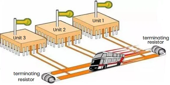
Figure 3: CAN Termination Resistor
The terminated resistors on the CAN bus are connected in parallel on the bus. Putting them at a remote computer or placing them alone can effectively absorb reflected waves. The resistance values of the two terminals in Figure 1 are both 120Ω. They are connected in parallel at both ends of the CAN twisted-pair bus, so the resistance between the high and low CAN lines should be 60Ω. If it is 120Ω, it means that a terminal resistor is disconnected. If the resistance between the two CAN lines is infinite, it means that the two terminal resistors are open; If it is zero, which means the two high and low buses are connected together and shorted. Once the terminating resistor is disconnected, the signal transmitted by the bus will be unstable because the interference wave cannot be effectively absorbed, which will directly affect the normal operation of the relevant computer.
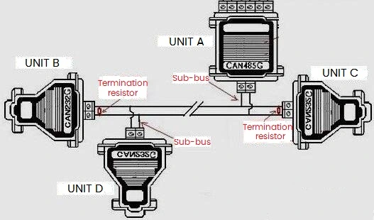
Figure 4: CAN Termination Resistors in Parallel
CAN Topology
CAN Topology Structure
The topology of high-speed CAN is as follows:
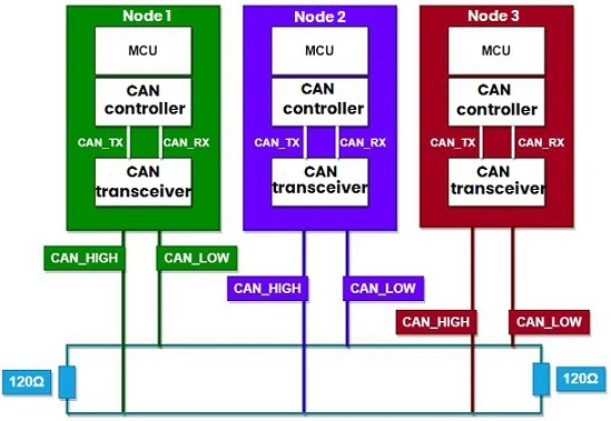
Figure 5: High-speed CAN Topology Structure
There is also a low-speed CAN, or also called fault-tolerant CAN. It reduces the maximum bandwidth of communication from 1 Mbps to 125 Kbps, and no longer uses two terminal resistors at the beginning and end of the bus, but distributes them on each node. Specifically as shown in the figure below:
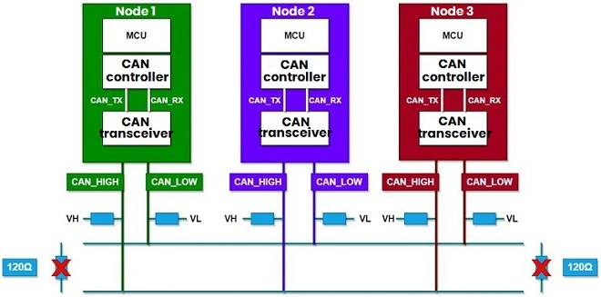
Figure 6: Low-speed CAN Topology Structure
Since the topological structure of high-speed CAN and low-speed CAN are different, and the distribution of terminal resistance is also different, so do the levels. And there are recessive levels and dominant levels.
Under CAN topology, if one of the terminations is removed, the impedances on the bus will no longer be perfectly matched. However, it can still be used normally in the case of short-distance transmission. Therefore, the CAN bus communication distance will be much smaller than the double-terminal topology.
CAN Nodes
CAN nodes are usually divided into three parts:
1) MCU/CPU
2) CAN controllers
3) CAN transceivers
Usually some single-chip microcomputers integrate corresponding CAN controller peripherals, such as our more commonly used single-chip microcomputer STM32, so our common structure is generally like this:
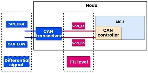
Figure 7: STM32-CAN Peripherals
So the overall process is like this, as follows:
1) Data transmission on the CAN bus through differential signals.
2) The CAN transceiver converts the differential signal into a TTL level signal, or converts the TTL level signal into a differential signal.
3) The CAN controller receives the TTL level signal and transmits it to the MCU.
Then, for microcontroller developers, what needs to be paid attention to is the data transmitted by the CAN controller to the MCU, how to configure the CAN controller, and use it to read and send data.
CAN Protocol
Speaking of this, we have to understand the communication principle of the CAN bus, how to address it, and how the upper layer protocol is stipulated. The CAN protocol is similar to the network protocol, and a layered design idea is carried out.
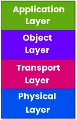
Figure 8: CAN Protocol Layers
1) The physical layer is the hardware topology mentioned above, including high-speed CAN and low-speed CAN, and the CAN transceiver belongs to the physical layer.
2) The transport layer is what the CAN controller needs to do, including CAN timing, synchronization, message arbitration, confirmation, error checking, etc., which are relatively complicated. The work to be done at this layer includes:
* Failure constraints
* Error monitoring
* Message verification
* Information confirmed
* Arbitration
* Info frame
* Transfer rate and time
* Routing information
3) As for the object layer, the MCU should belong to it. We need to filter the CAN messages, process the CAN messages, etc.
4) The application layer is further encapsulation based on the object layer, different CAN standards, such as CANopen in the field of industrial automation, UDS defined in ISO 14229 for automotive diagnostics, etc.
Note:
* CANOpen
It is a high-level communication protocol, including communication sub-protocol and device sub-protocol. It is often used in embedded systems and is also a field bus commonly used in industrial control.
CAN Bus Addressing
Each node on the CAN bus does not need to set the address of the node, but distinguishes the info through the identifier of the message. Because the messages on the CAN bus are broadcast (that is, everyone can receive the messages), for example, if there are nodes A, B, and C on the bus, then node A sends a message, and both node B and node C will receive it.
Node B and node C will compare according to the identifier in the message and filtering rules in B and C. If the rules are not satisfied, the information will not be accepted.
It should be noted here that when sending a message, the bus must be in an idle state; the smaller the identifier, the higher the priority of the message acquisition bus.
CAN Frames
Now that you know how to address, let's take a look at the message frame: CAN communication messages are carried out in 4 types of frames.
Data frame: used for the communication node to transmit data to the outside.
Remote control frame: used to request data from remote nodes.
Error frame: used to notify the remote node of a verification error and request to resend the previous data.
Overload frame: used to notify the remote node: this node is not ready to receive.
1. Data Frame
It consists of seven different bit fields:
Start of Frame, Arbitration Field, Control Field, Data Field, CRC Field, ACK Field, End of Frame.
|
Start of Frame
|
Arbitration Field
|
Control Field
|
Data Field
|
Calibration Field
|
ACK Field
|
End of Frame
|
|
COB-ID
|
RTR
|
|
1 bit
|
11 or 29 bits
|
1 bit
|
6 bits
|
0~8 byte
|
16 bits
|
2 bits
|
7 bits
|
2. Remote Frame
The remote frame also has a standard one and an extended one, and is composed of 6 different bit fields: start of frame, arbitration field, control field, CRC field, response field, and end of frame. Compared with the data frame, the RTR bit of the remote frame is recessive, there is no data field, and the data length coding field ranges from 0 to 8 bytes. When a data frame and a remote frame with the same arbitration field are sent at the same time, because the RTR bit of the data frame is dominant, the data frame gets priority. And nodes that send remote frames can receive data directly.
3. Error Frame
An error frame consists of two different fields: the first field is an error flag from the controller; the second field is an error delimiter.
1) Error flag: There are two forms of it.
① Activate error flag: It consists of 6 consecutive dominant bits.
② Passive error flag: It consists of 6 consecutive recessive bits.
Note: It can be rewritten by dominant bits of other CAN bus protocol controllers.
2) Error delimiter:
It consists of 8 recessive bits. After transmitting the error flag, each station sends a recessive bit, and monitors the bus until a recessive bit is detected, and then begins to send the remaining ones.
4. Overload Frame
It consists of two areas: an overload identification field and an overload delimiter field. The following three states will cause overload frame transmission:
1) The receiver needs too much time to process the current data before receiving a frame (the reception is not ready).
2) A dominant bit signal is detected in the frame gap field.
3) If the CAN node samples a dominant bit in the 8th bit of the error delimiter or overload delimiter, it will send an overload frame.
5. Message Format
In the message transmitted in the bus, each frame consists of 7 parts. The CAN protocol supports two message formats, the only difference is that the identifier (ID) length is different, the standard format is 11 bits, and the extended format is 29 bits.
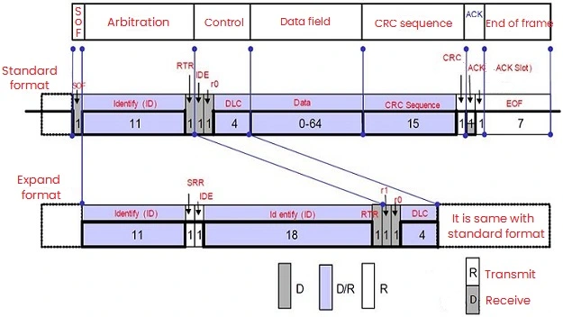
Figure 9: CAN Frame Structure
In the standard format, the start bit of the message is called the start of frame (SOF), followed by an arbitration field consisting of an 11-bit identifier and a remote transmission request bit (RTR). The RTR bit indicates whether it is a data frame or a request frame, and there are no data bytes in the request frame.
The control field includes the identifier extension bit (IDE), indicating whether it is a standard format or an extended format. It also includes a reserved bit for future expansion. And its last four bits are used to indicate the length of the data in the data field, which ranges from 0 to 8 bytes, followed by a cyclic redundancy check (CRC) for detecting data errors.
The acknowledgment field (ACK) consists of a bit and a delimiter. The two bits sent by the sending station are recessive levels (logic 1), and the receiving station that correctly receives the message sends a master control level (logic 0) to cover it. In this way, the sending station can guarantee that at least one station in the network can receive the message correctly.
The end of the message is marked by end-of-frame. There is a very short interval bit between two adjacent messages. In addition, if no station performs bus access at this time, the bus will be in an idle state.
6. Message Timing and Synchronization
CAN belongs to asynchronous communication and has no clock signal line, so all nodes must agree to use the same baud rate to transmit data. After the bus has been idle for a period of time, hard synchronization is performed on (start bit). The related method is to divide each bit into multiple time quanta, and assign a certain number of quanta to the four phases in the bit.
Include:
1) SYNC_SEG: Synchronization segment, 1 time quantum length. It is used to synchronize various bus nodes.
2) PROP_SEG: Propagation segment, 1~8 time quantum length. It is used to compensate for signal delays on the network.
3) PHASE_SEG_1: Phase buffer segment 1, 1~8 time quantum length. It is used to compensate for edge phase errors, which may be extended during resync.
4) PHASE_SEG_2: Phase buffer segment 2, 2~8 time quantum length. It is used to compensate for edge phase errors.
7. Message Filter
It was mentioned earlier that messages are broadcast on the CAN bus, but not all nodes are interested in all messages on the bus. The node judges whether to receive the message through the filter code and mask code in the controller, and then checks the identifier of the message on the bus.
For the mask, "1" indicates that the bit is relevant to this node, and "0" indicates that the bit is not relevant to this node. Examples are as follows:
Example 1: Receive only frames with message identifier 00001567 (hexadecimal)
Set the filter code to 00001567
Set the mask to 1FFFFFFF
The node detects all bits (29 bits) of the identifier of the message. If the identifier is 00001567, it is received, otherwise it is filtered.
Example 2: Receive frames with message identifiers 00001567 to 0000156F
Set the filter code to 00001560
Set the mask to 1FFFFFF0
The upper 25 bits and the lowest 4 bits of the identifier of the node detection message are ignored. If the highest 25 bits of the identifier are the same, then accept it, otherwise discard it.
Example 3: Receive frames with message identifiers 00001560 to 00001567
Set the filter code to 00001560
Set the mask to 1FFFFFF8
The upper 26 bits and the lowest 3 bits of the identifier of the node detection message are ignored. If the highest 26 bits of the identifier are the same, then accept it, otherwise discard it.
Example 4: Receive all message frames
Set the filter code to 0
Set the mask to 0
Nodes receive all messages on the bus.
8. Bus Conflict
As mentioned above, the arbitration frame indicates the priority segment. When two messages are sent at the same time, the bus will determine which data packet can be transmitted according to the ID of the arbitration segment. During it, each transmitter compares the level of the transmitted bit with the monitored bus level. If the levels are the same, the unit can continue to send. If the "recessive" level is sent but the "dominant" level is monitored, then the unit loses arbitration and must exit the sending state.
For example, two messages of ID18 and ID19 are sent at the same time:
|
A(ID18)
|
0
|
0
|
1
|
0
|
0
|
1
|
0
|
|
B(ID19)
|
0
|
0
|
1
|
0
|
0
|
1
|
1
|
|
Bus Level
|
0
|
0
|
1
|
0
|
0
|
1
|
0
|
From this table, we can see that during the process of sending the ID identifier, the bus voltage is the same as the level of the sent bit when the first few bits are sent, and the bus voltage of unit B is different from the level of the sent bit when the last bit sent, so B with low priority fails to blank and exits.
CAN Bus Summary
(1) The data on the Message bus is sent in different formats, but the length is limited.
(2) Information Routing is in CAN, and nodes do not use any messages related to system configuration.
(3) The message to be transmitted has a characteristic identifier (a field of a data frame and a remote frame), which gives not the address of the target node, but the characteristics of the message itself.
(4) Data consistency should ensure that the message is received or not by all nodes in the CAN at the same time, which is realized with the error handling and resynchronization functions.
(5) CAN systems with different bit transmission rates have different speeds, but in a given system, the bit transmission rate is unique and fixed.
(6) The priority of the message occupying the bus is determined by the identifier in the message, the smaller the identifier, the higher the priority.
(7) Remote Data Request needs send a remote frame, that is, a node requests another node to send corresponding data.
(8) For Arbitration, as long as the bus is idle, any node can send a message to the bus.
(9) The bus has two states of "dominant" and "recessive". The CAN bus adopts the binary non-return-to-zero (NRZ) encoding method, so the bus is either "0" or "1", and "dominant" corresponds to logic "0", "recessive" corresponds to logic "1". However, the CAN protocol does not specifically define the specific implementation of these two states.
(10) As for confinement, CAN nodes can distinguish between faults caused by transient disturbances and permanent faults.
(11) The response receiving node gives a note to the correctly received message, and marks the inconsistent message.
(12) The number of nodes on the CAN bus can reach 110.
(13) The message has a short frame structure, and the short transmission time has a low probability of interference.

 English










