A coupling capacitor is used to transmit an alternating current (AC) signal from one node to another. When designing a circuit, in some cases, you only want to transmit an AC signal, not a DC signal. At this time, you can use a series capacitor to couple the signal. For example, in a multi-stage amplifier, in order to prevent the interaction of DC biases, the calculation of the static operating point is complicated, and capacitive coupling is usually used between stages, so that each stage can be analyzed independently. For high-speed serial signals such as PCIE and SATA, capacitors are usually used for AC coupling.
AC-coupling Capacitor in High-speed Differential Interfaces
Capacitor Circuits Explained
In the hardware design, AC coupling capacitors are used in many high-speed differential interfaces. Since any small difference will cause signal integrity problems when designing high-speed serial circuits, why should they be used in serial links? What about adding an AC coupling capacitor? Because coupling capacitance will cause the signal edges to slow down, and it can also cause impedance discontinuities, as follows:
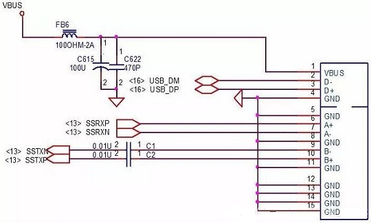
Figure 1: The 0.1uF Capacitor of the TX Signal in the USB3.0 Interfaces
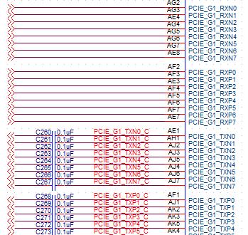
Figure 2. The 0.1uF Capacitor of the TX Signal in the PCIe Interfaces
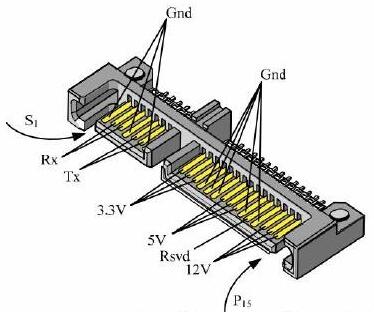
Figure 3. The 0.01uF Capacitor of the RX and TX Signals in the mSata Interfaces
Common low-speed signals such as 232 and LPC do not have AC coupling capacitors, as follows:
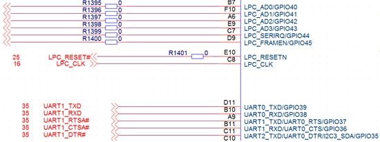
Figure 4: No Capacitance in UART, LPC Interface Signals
The Role of AC Coupling Capacitors
1. The source and sink DCs are different, so DC is blocked.
2. When the signal is transmitted, there may be crosstalk into the DC component, so blocking the DC makes the signal eye pattern better.
3. AC coupling capacitors can also provide DC bias and overcurrent protection. In short, the role of the AC coupling capacitor is to provide a DC bias, filter out the DC component of the signal, and make the signal symmetrical about the 0 axis.
4. Adding the AC coupling capacitor is definitely to enable better communication between the two stages and can improve the noise margin.

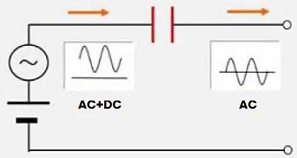
Figure 5: Adding AC Coupling Capacitors Improves Noise Margin
How Does AC-coupling Capacitor Improve Noise Margin?
Sometimes we may choose a small capacitor, thinking that this may filter the DC component more cleanly, but this will cause signal distortion and baseline drift; if a larger capacitor is selected, the time for the voltage at the capacitor terminal to stabilize is relatively long. There are so many particulars about such a capacitor, so how should we choose one? First of all, it depends on the frequency, temperature, low ESR/ESL and other characteristics. Then the capacitance value should be calculated, as follows:

Here F is the cutoff frequency (at which the voltage is defined as 0.707 times the input voltage), R is the impedance of the transmission line, and C is the AC coupling capacitance.
When selecting a capacitor, the minimum frequency of its passband should be smaller than the minimum frequency of the transmission signal. Assuming that the minimum frequency of the signal is Fmin, the frequency value is: F=Fmin/20
When the value is F, 99.88% of the signals will pass.
As mentioned earlier, although the AC coupling capacitor has its benefits, it will also cause the edge to slow down. When the AC coupling capacitor is placed, it will cause a change in impedance, and there is an impedance discontinuity point. At the same time, pattern-related jitter will also be existed, that is, when continuous "1" or "0" appears in the signal transmitted by the circuit, the DC level voltage drop shown in the figure below will appear, which will affect the eye height.
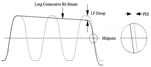
Figure 6: Lwo-frequency Pattern-dependent Jitter Caused by AC-Coupling
How can we reduce this DC voltage drop? This is related to the RC time constant. The larger the RC value (the longer the charging time, the less capacitor charging per unit time, and the smaller the divided voltage), the more DC components that can pass through and the smaller the DC voltage drop. Since the equivalent resistance in the link is relatively fixed, only the value of the coupling capacitance can be adjusted. As shown in the figure below, the larger the capacitance value, the smaller the voltage drop.
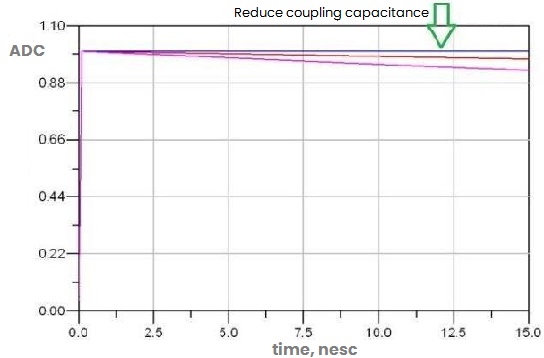
Figure 7: The larger the capacitance, the smaller the voltage drop
Curve Description: The purple capacitance value is the largest, the red capacitance value is the second, and the pink capacitance value is the smallest.
On the contrary, when the capacitor is infinitely increased? Of course, this is impossible, because there is no ideal capacitor in reality. In addition to ESR, ESL, there is also an installed inductance, so there is a series resonance frequency (SRF). Before it, the alternating current that reaches its maximum value up to later than the voltage that generates it. When having SRF, the current lags the voltage. As shown below:
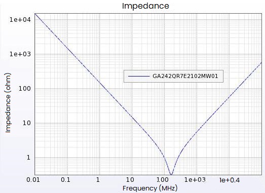
Figure 8: Relationship Between Frequency and Impedance
The larger the capacitance value, the smaller the resonant frequency, and the capacitance will be inductive at lower frequencies, which will increase the attenuation of high-frequency components of the signal, reduce the eye height, slow the rising edge, and increase jitter.
Therefore, when choosing an AC coupling capacitor, the above two points should be considered. Generally, the industry recommends 0.01uF~0.2uF, and the most common one is 0.1uF. For the choice of capacitor package, it is not recommended to use a package larger than 0603, preferably 0402, or smaller.
How to Place the AC Coupling Capacitor?
Generally speaking, we use AC coupling capacitors to provide DC bias voltage, which is to filter out the DC component of the signal and make the signal symmetrical about the 0 axis. Can this capacitor be placed anywhere in the channel?
Here is an analysis of a typical path that is often encountered.
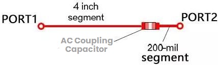
Figure 9: Typical Path of an AC Coupling Capacitor
In low-speed circuit design, such capacitor can be equivalent to an ideal capacitor. In high-frequency circuits, due to the existence of parasitic inductance and the impedance discontinuity caused by the plate, in fact this capacitor cannot be regarded as an ideal one. Here the signal frequency is 2.5G, the channel length is 4000mil, and the position of the AC coupling capacitor is 200mil away from the sending end and the receiving end respectively. Let's take a look at the changes in the simulated eye pattern.
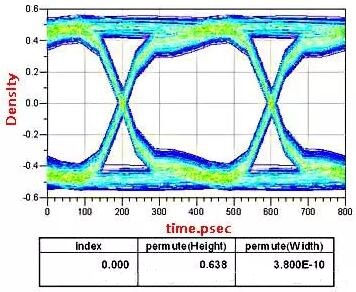
Figure 10: Eye Pattern of AC Coupling Capacitor Near to Transmitter
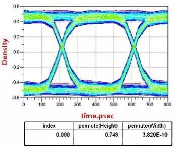
Figure 11: Eye Pattern of AC Coupling Capacitor Near to Receiver
Obviously, the signal integrity is better when the AC coupling capacitor is near the receiving end than when it is placed at the sending end. Here the impedance of a non-ideal capacitor is discontinuous, and the reflected energy after the signal is attenuated by the channel will be less than the directly reflected energy, so most serial links require this AC coupling capacitor to be placed at the receiving end. But there are exceptions. When making board-to-board connections, checking the PCIe specification, you will find that if two boards are usually placed on the sending end, another function of the AC coupling capacitor introduced - overvoltage protection. For example, SATA, so it is usually required to be placed close to the connector.
After solving the problem of placement, another problem that bothers people is the selection of capacitance. In this way, the equivalent resistance R of our entire serial link is fixed, so the selection of the AC coupling capacitor will be related to the time constant (RC). The larger the RC, the larger the passing DC component, and the lower the DC voltage. In this case, can the AC coupling capacitor be infinitely increased? Obviously not.
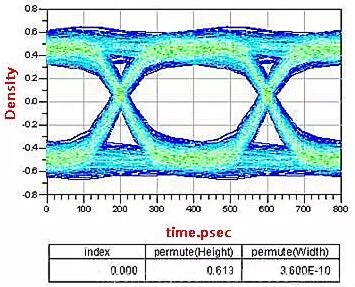
Figure 12: Measured Eye Pattern with Increased AC Coupling Capacitance
In the same position, compared with Figure 12, it can be seen that after increasing the coupling capacitor, the eye height becomes lower. The reason is that "high speed" makes the capacitor less than ideal. Inductive inductance will produce series resonance, the larger the capacitance, the lower the resonant frequency, and the AC coupling capacitor is inductive at low frequencies, so the attenuation of high-frequency components increases, that why the eye height becomes smaller, the rising edge becomes slower, and the corresponding jitter also increase. It is usually recommended that select the AC coupling capacitance within the range of 0.01uf and 0.2uf, and 0.1uf is more common in projects.
Finally, after solving the above two problems, analyze the optimal design of this capacitor for PCB design. In fact, in the project, compared with the visible factors such as the position and capacitance of the AC coupling capacitor, what is more elusive is the board itself (including the accuracy of the pad, the uniformity of the copper foil, etc.) and the impact on signal integrity of parasitic capacitance at the pad. We know that high-frequency signals must propagate along a path with uniform characteristic impedance. If impedance mismatch or discontinuity occurs, part of the signal will be reflected back to the transmitter, causing signal attenuation and affecting signal integrity. In the PCB project, this situation usually occurs at the pad or the on-board connector.
To solve this problem, we must start from two aspects. First of all, in the selection of the plate, we usually choose the high-performance plate in the application. It is very precise in the control of the thickness of the copper foil. The uniform copper foil coverage greatly reduces the discontinuity of the impedance. For the parasitic capacitance at the pad, the common method in the industry is to do interlayer processing at the pad (hollow out the reference plane area directly below the pad, and create copper filling in the inner layer), that is, by increasing the pad and its reference plane ( or the distance between the return path) to reduce the discontinuity of the capacitance.
Through simulation, compare the signal integrity of the plate before and after precise interlayer processing.
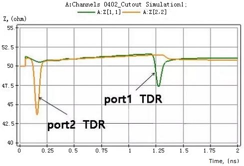
Figure 13: TDR Before Have Interlayer Processing
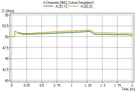
Figure 14: TDR with Interlayer Processing
Comparing the above two figures, it is found that the jump of the impedance before the treatment is obvious, and the impedance after the interlayer treatment is greatly improved, and there is almost no step and discontinuity.
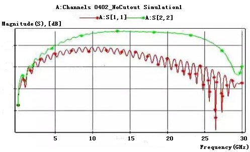
Figure 15: Return Loss Before Interlayer Processing
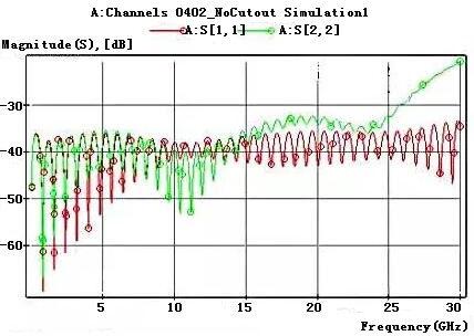
Figure 16: Return Loss After Interlayer Processing
Comparing the above two pictures, after using the plate with interlayer treatment, the return loss drops to within -30dB compared to that without it, which greatly reduces the return loss and ensures the integrity of signal transmission.
Conclusion
1. Follow the agreements or manuals which will provide design requirements.
Generally speaking, the position and capacitance of the AC coupling capacitor are provided by the signal protocol or the chip supplier. For different signals and different chips, the position and capacitors are different. For example, the PCIe signal requires the AC coupling capacitor to be close to the transmitting end of the channel, and the SATA signal requires the AC coupling capacitor to be close to the connector.
2. If it is IC to IC, please place it close to the receiving end.
The capacitor is regarded as an impedance discontinuity point (so it is required to match the transmission line as much as possible). If it is placed close to the receiving end, under the same reflection coefficient, the reflected energy after the signal is attenuated by the channel will be smaller than the reflected energy at the beginning. So most of the serial links are required to rely on the receiving end to put.
In the process of signal transmission, some DC components may also be crosstalked, causing problems in reception, so it is close to the receiving end. After AD simulation, it is also found that the quality of the eye pattern at the receiving end is better.
3. If it is IC to connector, please place it close to the connector.
We know that the AC coupling capacitor has another function, which is to provide overvoltage and overcurrent protection. So in the case of a connector, the capacitor should near it.
4. Choose the smallest package size possible to reduce impedance discontinuity.
5. What should be paid attention to when AC coupling capacitors are designed in PCB?
The AC coupling capacitor is generally a point where the high-speed signal impedance is discontinuous, and solving it is the focus of its design.
1) There will be attenuation in the process of SATA signal transmission, the longer the transmission distance, the more severe the attenuation will be, so it will be given a carrier (that is, DC component), and then use the method of series capacitors after entering the IC or SATA device to filter out the DC component, which will have a better signal quality, that is, the DC blocking effect.
2) It is stipulated by the protocol that PCIE is placed on the sending end. Remember that capacitor is placed on the near-end TX to perform charging detection for the detector.

 English










