A film capacitor is a capacitor that uses metal foil as an electrode, overlaps it with a plastic film such as polyethylene, polypropylene, polystyrene, or polycarbonate from both ends, and then winds it into a cylindrical structure. Depending on the type of plastic film, they are also called polyethylene capacitors (also known as Mylar capacitors), polypropylene capacitors (also known as PP capacitors), polystyrene capacitors (also known as PS capacitors) and polycarbonate capacitors. It is generally used for high-frequency filtering, high-frequency bypass, first-order or second-order filter circuits. In addition, all current film capacitors have no polarity, that is, they do not need to distinguish between positive and negative electrodes.
Film Capacitor Basic
Film Capacitor Structures
1. Two Main Structures
If divided according to the internal structure of film capacitors, we can divide film capacitors into wound structure and laminated structure:
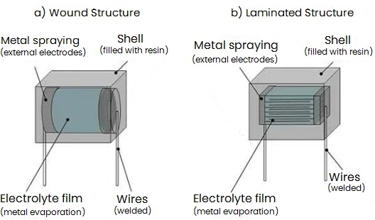
Figure 1: Film Capacitor Internal Structures
The material of wound type is polymer film that rolled and punched, and then put into a shell. While the laminated type has multiple layers of polymer films are laminated together and then placed in a shell. Nowadays, most film capacitors basically use wound structure, because this structure is easy to manufacture.
Film capacitors with a laminated structure, such as CL71 correction capacitors, are commonly used. However, the production equipment of this type is complex and extremely expensive, and the product defect rate is relatively high. Now they are slowly being replaced by CL23B wound capacitors. In short, truly laminated film capacitors are now extremely rare to see.
2. Inner Core Structures
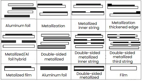
Figure 2
Film Capacitor Features
* Advantages
1) Large insulation resistance and good heat resistance.
2) Self-healing and non-sensitive properties.
3) It has excellent high-frequency insulation properties. Its capacitance and loss angle are independent of frequency within a large frequency range, and changes very little with temperature, but the dielectric strength increases with temperature.
4) High temperature resistance and small absorption coefficient.
* Disadvantages
Large size, higher price, poor high temperature characteristics.
Materials Selection
When selecting, film capacitors of different materials have different characteristics.
1. Polyester (PET)
1) High mechanical strength, easy film formation (the thinnest can reach 0.6um), good tensile strength, high elasticity, and good flexibility.
2) Good heat resistance (the maximum working temperature can reach 125°C), at high temperatures, the film is still flexible and does not become brittle at - 60°C.
3) Large dielectric constant.
4) Easy to metallize and have high volume ratio.
5) However, compared with other plastic films, the volume resistivity of PET film is lower and the loss tangent is also larger. When the service temperature is higher than 100C, its volume resistivity plummets and the loss tangent value also increases rapidly. If the operating temperature requirements are higher, PEN materials can be selected.
6) Moderate moisture resistance, which decreases at low temperatures.
7) Excellent heat resistance, cold resistance, good chemical resistance and oil resistance, but it is not resistant to strong alkali.
8) Easily charged with static electricity.
2. Polypropylene (OPP)
1) It has high water resistance, is not corroded by strong acids and alkalis, and has strong resistance to organic solvents.
2) Excellent electrical properties, high dielectric strength, small loss tangent value, and little relationship with temperature and frequency.
3) It is easily corroded by light, heat and oxygen in the air, causing the medium to age and deteriorate its performance.
4) Temperature resistance is relatively poor.
3. Film/Foil Capacitors & Metallized Film Capacitors
The difference between foil film type and metallized film type
1. Characteristics of foil film capacitors:
1) High current strength
2) No self-healing ability, withstand peak voltage difference
2. Characteristics of metallized film capacitors:
1) Good self-healing and strong voltage resistance
2) Poor current resistance
Models and Applications Introduction
1. Specifications
1) CL-polyester film capacitor
For example: CL11 (sensitive foil polyester film capacitor), CL21 (metallized polyester film capacitor)
2) CBB-polypropylene film capacitor
For example: CBB21 (metallized polypropylene film capacitor), CBB81 (high voltage metalized polypropylene film capacitor)
* Manufacturing process
1) Sensitive foil type CL11/CBB11
2) Metalized coiled CBB21, etc.
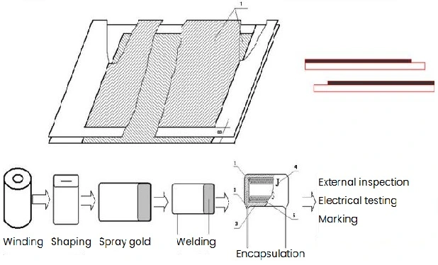
Figure 3: Metallized Wound Film Capacitor
2. Applications
1) Filtering
The film capacitor in rectifier circuit converts AC into pulsating DC, and the filtered pulsating DC voltage becomes a relatively stable DC voltage.
2) Reduce noise
Noise interference outside the system sometimes occurs in the current, at this time, the capacitor can reduce the noise interference outside the system.
3) Suppress and buffer EMI
During system operation, sudden current and signal interference often occur, here EMI filters with film capacitor can reduce the interference current and signal that suddenly enter the system.
4) DC support DC-link
Generally needed in AC to DC conversion, it plays the role of filtering and energy storage to support the stability of DC circuits. This is a more important application for film capacitors in various types of converters. The downstream includes inverters, rectifiers, AC converters, DC converters, etc., which are necessary in downstream fields such as electric vehicles, photovoltaic wind power, energy storage, and industrial power supplies.
5) Energy storage
The film capacitor temporarily stores the power of the system and releases a higher instantaneous current when the system needs it.
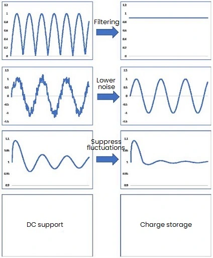
Figure 4: Film Capacitor Applications
Film capacitors are mainly used in electronics, home appliances, communications, electric power, electrified railways, hybrid vehicles, wind power generation, solar power generation and other industries. The stable development of these industries has promoted the growth of the film capacitor market. Its selection should be considered based on the specific use environment and needs. When selecting, attention should be paid to factors such as capacitance value, packaging form, operating voltage, temperature coefficient, and lifespan.
Technical Parameters
1. Capacity
Capacitance represents the amount of electrical energy stored in a capacitor and should be selected based on the actual application.
2. Loss tangent
This represents the proportion of electrical losses in the capacitor. If a voltage is applied to a capacitor, in addition to the current that charges the capacitor, there is also a leakage current, which is consumed as heat energy, so it is expressed as a current on the resistor. The ratio of the leakage current to the charging current of a pure capacitor is the tangent of the capacitor loss angle (in theory, a pure capacitor consumes no power). The smaller the ratio, the better the performance of the capacitor.
3. Voltage resistance
The maximum DC voltage that a capacitor can withstand is the withstand voltage of the capacitor, which is also called the DC working voltage of the capacitor.
4. Rated voltage
The maximum DC voltage or pulse voltage peak allowed for continuous operation of the capacitor within the rated temperature range.
World Famous Brands
1) Nichicon
2) Panasonic
3) Hitachi
4) Vishay
5) Yageo
6) Rubycon
7) EPCOS
8) Würth Elektronik
9) Nippon Chemi-Con
10) Kemet Corporation
Capacitors Comparison
1. Film Capacitors vs Electrolytic Capacitors
|
Parameters
|
Film Capacitors
|
Electrolytic Capacitors
|
|
Capacitance
|
Smaller, uF level
|
Larger, uF or F class
|
|
Medium
|
Metallized film
|
Aluminum oxide (Al foil corrosion)
|
|
Dielectric Coefficient
|
2.2+0.2
|
8~8.5
|
|
Media Status
|
Solid state
|
Liquid
|
|
Working Voltage (Max)
|
Thousands of volts
|
Generally 450V
|
|
Overvoltage Resistance
|
2.0 Un
|
1.15~1.2 Un
|
|
Polarity
|
NO
|
YES
|
|
Continuous Current Resistance Capability (rms)
|
200mA/uF~1A/uF
|
20mA/uF
|
|
Voltage Ramp Rate (dv/dt)
|
High
|
Low
|
|
Service Life
|
More than 80,000-100,000 hours
|
Usually 3-5 years
|
|
Charge Storage
|
No storage problems, performance basically unchanged.
|
Long-term storage leakage current will increase and capacity will decrease.
|
In addition, film capacitors have self-healing ability, and a single defect will not affect the normal use of the entire film capacitor; the lower ESR can withstand larger ripple currents; the lower ESL fits the inverter busbar well; the low inductance design requirements reduce the voltage spike during IGBT switching action; the size and shape of the film capacitor can be customized according to the structural characteristics of your own product.
2. Film Capacitors vs Ceramic Capacitors
* Film Capacitors:
Thin film capacitors use thin films on metal or semiconductor substrates to form electrodes and dielectric layers. They have the advantages of controllable capacitance, high temperature resistance, and uniform quality. However, its size is larger and its price is higher than ceramic capacitors, so it is not suitable for precision circuits.
* Ceramic Capacitors:
Ceramic capacitors are mostly made of alumina ceramic materials, which have the characteristics of small size, stable capacitance value under temperature changes, and low price. Also, they have shortcomings, like large relative dielectric constant, low Q value, large noise, and cannot withstand high voltage and high frequency.

 English










