Inductor (coil) is a device that uses the principle of electromagnetic induction to work. In electronics, it mainly isolates and filters AC signals or forms a resonant circuit with capacitors and resistors to play multiple roles such as energy storage, current limiting, and voltage transformation.
Coil is a property of a closed loop and a physical quantity. When the current passes through the coil, a magnetic field is induced in it, and then generates an induced current to resist the current passing through the coil. In short, it is a circuit parameter that describes the induced electromotive force effect caused in a inductor or another one due to changes in coil current.
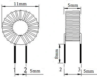
Inductor Basic
Working Principle
For an inductor, when a current flows through a wire, a certain electromagnetic field will be generated around it, and the wire itself of this electromagnetic field will induce the wires within the range of this electromagnetic field, which is called "self-induction", that is, the changing current generated by the wire itself produces a changing magnetic field, which further affects the current in the wire; the effect on other wires within the range of this electromagnetic field , called "mutual induction". The impedance presented by the inductor to the current signal shows the self-inductance of the coil.
When DC current passes through the inductor, only fixed magnetic lines of force appear around it, which do not change with time. However, when AC current passes through the coil, magnetic lines of force change with the time. According to Faraday's law of induction, changing magnetic field lines will generate induced electric potential at both ends of the coil. When a closed loop is formed, this induced potential will produce an induced current.And meanwhile, from Lenz's law, we know that the total amount of magnetic field lines generated by the induced current will prevent the change of the original magnetic field lines. Since the change of magnetic field lines originally comes from the change of external alternating power supply, it can be inferred from the above that the inductor coil has the characteristic of preventing the change of current in the AC circuit. The inductor coil has characteristics similar to inertia in mechanics.This is the self-induction mentioned above. For example, sparks will occur at the moment when the switch is turned on or off because of high induced potential.
In addition, the electrical characteristics of the inductor are opposite to those of the capacitor, that is "passing low frequencies and blocking high frequencies." When high-frequency signals pass through the inductor coil, they will encounter great resistance and are difficult to pass; while when low-frequency signals pass through it, the resistance is relatively small, and the resistance of an inductor to DC current is almost zero.
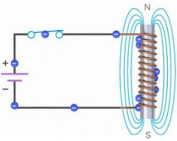
Figure 2: Inductor (Coil) Principle Diagram
Performance Parameters
The performance parameters of the inductor is mainly the inductance. In addition, the wires wound around the inductor generally have a certain resistance, which is very small and can be ignored. But when the large current flowing through some circuits, it cannot be ignored, because the large current will consume power on the coil, causing the coil to heat up or even burn out, so sometimes it must be considered the electrical power that the coil can withstand.
1) Inductance
The inductance L represents the major characteristics of the coil itself and has nothing to do with the size of the current. Except for special coils (color-code one), the inductance is generally not specifically marked on the coil, but is marked with a specific name. Inductance is also a physical quantity that represents the self-induction ability of an inductor. And it mainly depends on the number of turns of the coil, the winding method, the presence or absence of a magnetic core and the material of the magnetic core, etc. Generally, the more turns, the greater the inductance. In addition, a coil with a magnetic core has a larger inductance than a coil without a magnetic core, and a coil with a larger magnetic core permeability has a larger inductance.
The basic unit of inductance is Henry, represented by the letter "H". Commonly used units include millihenry (mH) and microhenry (μH). The relationship between them is: 1H=1000mH, 1mH=1000μH
2) Resistance
The resistance effect of the inductor on the AC current is called inductive reactance XL, and its unit is ohms(Ω). Its relationship with the inductance L and the AC frequency f is XL=2πfL
3) Quality factor Q
Q represents the quality of the coil, and it is the ratio of the inductive reactance XL to its equivalent resistance, that is, Q=XL/R. It refers to the ratio of the inductive reactance presented by the inductor to its equivalent loss resistance when operating under an AC voltage of a certain frequency. The higher the Q value, the smaller its losses and the higher its efficiency.
Also the Q is related to the DC resistance of the wire, the dielectric loss of the skeleton, the loss caused by the wires or iron core, the influence of high-frequency skin effect and other factors. Usually, the Q value of the coil is usually tens to hundreds.
4) Distributed capacitance
In any coil, there is a certain capacitance between the turns, the layers, the reference ground, and the magnetic shield, etc. And they are also called the distributed capacitances of the inductor coil. If they are combined together, which become an equivalent capacitance C in parallel with the inductor coil. Further more, the existence of them reduces the Q value of the coil and worsens the stability. Therefore, the smaller the distributed capacitance of the coil, the better.
5) Rated current
It refers to the maximum current value that is allowed to pass through the inductor when it is operating normally. If the operating current exceeds it, the performance parameters of the inductor will change due to heat generation, and may even burn due to overcurrent.
6) Allowable deviation
It refers to the allowable error value of inductor between the nominal inductance and the actual inductance. Usually, inductors used in circuits such as oscillation or filtering require high precision, and the allowable deviation is ±0.2[%]~±0.5[%]; while the precision requirements for coils used in coupling, high-frequency blocking, etc. are not high, and allowable The deviation is ±10[%]~15[%].
Classifications
Air core coil: It is the simplest coil inductor, its coil consists of wires wound on a hollow tube. It has high self-inductance value and stability and is often used in radio frequency circuits and tuned circuits.
Iron core coil: It uses an iron core or soft magnetic material as the core of the coil. Because of it, the induction capacity and energy storage capacity of the coil increase, making it widely used in transformers.
Multi-layer winding coil: It has higher self-inductance value and inductance capacity. By winding the wire into a multi-layer spiral or parallel winding, the sensing area of the coil can be increased and the inductance value can be improved.
Mutual induction coil: It is composed of multiple coils connected by magnetic coupling. And it can realize the transmission of current and the transfer of energy, which is widely used in transformers, filters, common mode inductors and other fields.
Adjustable coil: It has the characteristic of adjustable inductance value. By changing the winding method or structure of the coil, different inductance values can be provided to adjust circuit parameters or meet different application requirements.
Applications
Energy storage: Coils can store electrical energy. When current passes through a coil, the magnetic field generated stores the energy in the magnetic field; when the current changes, the magnetic field releases it.
Filtering: Coil has impedance characteristics for AC circuits, which can block high-frequency signals from passing through and allow low-frequency signals to pass through. Therefore, in filter circuits, coils can be used to filter out noise or selectively pass signals of a certain frequency.
Suppressing interference: Because the coil has impedance characteristics, it can play a role in isolating and suppressing interference in the circuit. For example, adding it to the power line can reduce the electromagnetic interference of the power supply and improve the stability and reliability of the system.
Transformation and Coupling: Coil plays an important role in transformers and couplers. Through the winding ratio of the coil, the voltage can be increased or decreased. At the same time, in signal transmission and coupling, a inductor can transfer signals from one coil to another.
Commonly Used Coils
1) Single-layer coil
It is made of insulated wires wound around a paper tube or bakelite frame. Such as the medium wave antenna coil of a transistor radio.
2) Honeycomb coil
If the plane of the wound coil is not parallel to the plane of rotation, but intersects at a certain angle, this coil is called a honeycomb coil. The number of times the wire bends back and forth during one rotation is often called the number of bending points. The more bending points, the smaller the distributed capacitance.
Its advantages are small size, small distributed capacitance, and large inductance. Honeycomb coils are wound using a honeycomb winding machine.
3) Ferrite core and iron powder core coil
The inductance of the coil is related to the magnetic core. Inserting a ferrite core into an air-core coil can increase the inductance and improve the quality factor of the coil.
4) Copper core coil
It is widely used in the ultra-short wave range. The inductance is changed by rotating the position of the copper core in the coil, and this adjustment is more convenient and durable.
5) Color coded inductor
It is an inductor with a fixed inductance, which is marked with a color circle in the same way as a resistor.
6) Choke
The coil that restricts the passage of alternating current is called a choke coil, which is divided into a high-frequency type and a low-frequency type.
7) Deflection coil
It is the load of the output stage of the TV scanning circuit, which requires high deflection sensitivity, uniform magnetic field, high Q value, small size, and low price.
Inductance Calculation
1) Single layer coil
The picture below shows the main dimensions of this coil marked.
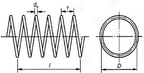
Figure 3: The Main Dimensions of Single-layer Coil
Where,
I - the length of the coil
D - the diameter of the coil
t - the turn spacing of the coil
d0 - the diameter of the wire
Calculated as follows:

Where,
L- the inductance
W - the number of turns of the coil
D - coil diameter (cm)
L0 - the correction coefficient of a single-layer coil, which is a quantity related to the length and diameter of the coil and can be obtained from the curve in the figure below.
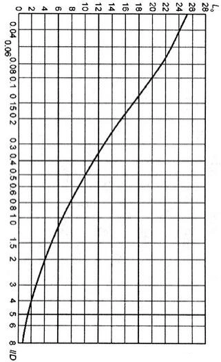
Figure 4: The Correction Coefficient of A Single-layer Coil
2) Multi-layer coil
The following figure marks the main dimensions of a multi-layer coil:
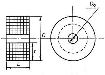
Figure 5: The Main Dimensions of Multi-layer Coil
Where,
D - the outer diameter of the coil
D0 - the inner diameter of the coil
L - the winding length
t - the radial thickness of the winding,
And the calculation formula is as follows:

The inductance of the multi-layer coil has nothing to do with the winding method. Therefore, the inductance of the honeycomb winding can also be calculated according to the calculation method of the multi-layer coil. The specific formula is as follows:

L - the inductance
W - the number of turns of the coil
D - the outer diameter of the coil (cm)
L0 - the correction coefficient of the multi-layer coil, which is different from the value of the single-layer coil and can be obtained from the curve in the figure below.
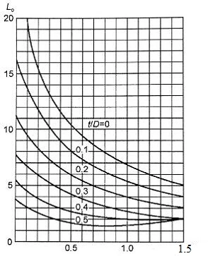
Figure 6: The Correction Coefficient of A Multi-layer Coil
3) With magnetic core
The calculation of the inductance of a coil with a magnetic core is related to the form of the magnetic core. Different forms of it require different calculation methods. In an ideal state, based on simple derivation, when the coil size, length, diameter and core material are selected, the desired parameters can be considered to be a certain value, which can be regarded as a constant. At this time, the inductance of the coil is only proportional to the square of its winding turns, so the following inductance calculation formula can be written:
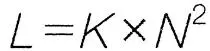
Where,
N - the number of turns of the coil
K - a coefficient, which is determined by the determined coil size and material.
When the inductance of the wound coil is a certain value Lm, you can first wind N0 turns on the skeleton (or directly on the magnetic core), use an inductance tester (or other tools) to measure the inductance L0, and then use the following formula to calculate K:
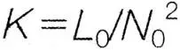
Then according to Lm and K, the number of turns N that the coil should be wound can be calculated, as follows:
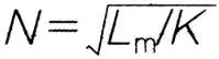
This method is just a simple calculation. After actual winding, the inductor can be measured and fine-tuned.

 English










