Rectifier circuits work simply by converting the AC power source into a DC power source. It is widely used in the fields of DC motor speed regulation, generator excitation regulation, electrolysis, electroplating and other fields. And the filter circuit is connected between the main circuit and the load to filter out the AC component in the pulsating DC voltage. Therefore, the rectifier circuit and the filter circuit appear together, both for the circuit to work normally and stably.
Rectifier Circuit
Working principle: Use the unidirectional conductivity of the diode in circuit to convert direct current into unidirectional pulsating direct current.
The characteristics of the single-phase rectifier circuit are shown in the table:
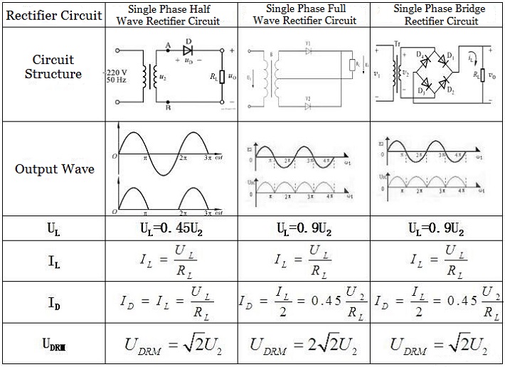
Figure 1: Single Phase Rectifier Circuit Characteristics
1. Single Phase Half Wave Rectifier Circuit
* Working principle
This type is the simplest rectifier circuit. Assume the effective value of the secondary voltage of the transformer is U2, then its instantaneous value u2=√2U2sinwt.
In the positive half cycle of u2, point A is positive and point B is negative. A forward voltage is applied to the diode, so it is in a conducting state. Where the current flows out from point A, then flows into point B through diode D and load resistor RL, so u0=u2=√2U2sinwt (wt =0~π).
In the negative half cycle of u2, point B is positive and point A is negative. A reverse voltage is applied to the diode, so it is in a cut-off state, u0=0 (wt=π~2π). Both the voltage and current of the load resistor RL have the characteristics of pulsating in one direction.
When analyzing the working principle of the rectifier circuit, the working state of the diode when the secondary voltage polarity of the transformer is different should be studied, so as to obtain the waveform of the output voltage and clarify the rectification principle.
* Main Parameters
1) Average output voltage UL=0.45U2
2) Load current average IL
3) When the effective value of the transformer secondary voltage and the load resistance value of the rectifier circuit are determined, the circuit's requirements for the diode parameters are also got. Generally, the diode model should be selected based on the average current flowing through the diode and the maximum reverse voltage it can withstand. In a single-phase half-wave rectifier circuit, the average forward current of the diode is equal to the average load current, which is ID.
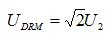
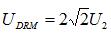
The maximum reverse voltage that the diode can withstand is equal to the peak voltage on the secondary side of the transformer, which is UDRM. In addition, the grid voltage is allowed to fluctuate by ±10%, so there should be at least 10% margin for the maximum rectified average current and the maximum reverse operating voltage.
The single-phase half-wave rectifier circuit is simple and easy to make and uses a small number of diodes. However, since it only utilizes half the cycle of the AC voltage, the output voltage is low, the AC component is large (the pulsation is large), and the efficiency is low. Therefore, this kind of circuit is only suitable for occasions where the rectified current is small and the requirements for pulsation are not high.
2. Single Phase Bridge Rectifier Circuit
The single-phase bridge rectifier circuit is composed of four diodes. The principle of its composition is to ensure that the direction of the voltage and current on the load remains unchanged during the entire cycle of the secondary voltage u2 of the transformer. In order to achieve this goal, it is necessary to correctly guide the current flowing to the load within the positive and negative half cycles of u2.
1) When u2 is a positive half cycle, the current flows out from point A and flows into point B through D1, RL, and D3.
2) When u2 is a negative half cycle, the current flows out from point B and flows into point A through D2, RL, and D4.
In this way, since the two pairs of diodes D1, D3 and D2, D4 conduct alternately, the load resistor RL has a current flowing through it during the entire cycle of u2, and the direction remains unchanged, and the output voltage uo=|√2U2sinwt|.
Since the bridge rectifier circuit implements a full-wave rectification circuit, it also takes the negative half cycle of u2, so when the effective value of the secondary voltage of the transformer is the same, the average value of the output voltage is twice that of the half-wave rectifier circuit. Moreover, when the secondary voltage of the transformer is the same and the load is the same, the average value of the output current is also twice that of the half-wave rectifier circuit.
In a single-phase bridge rectifier circuit, because each diode only passes current during half the cycle of the secondary voltage of the transformer, the average current of each diode is only half of the average current on the load resistor. It is the same as the average current of the diode in the half-wave rectifier circuit (although the load current is doubled, the diodes work in turns, so the average current flowing does not change).
Compared with the half-wave rectifier circuit, the single-phase bridge rectifier circuit has the same parameter requirements for the diode under the same transformer secondary voltage, and it also has the advantages of high output voltage, high transformer utilization, and small pulsation. With the development, there are currently integrated circuits with different performance indicators, which are called "rectifier bridge stacks". And its main disadvantage is that it requires a large number of diodes. Since the forward resistance of the diode is actually not zero, the internal resistance of the rectifier circuit will inevitably be larger, and of course the loss will be larger.
3. Calculations
|
Circuit Forms
|
Uo (no load)
|
Uo (with load)
|
Maximum reverse voltage that the diode can withstand UDRM
|
|
Half Wave Rectifier Circuit
|

|

|
|
|
Full Wave Rectifier Circuit
|
|

|
|
|
Bridge Rectifier Circuit
|
|
|
|
Note: The rectifier circuit is followed by capacitor filtering, when the load is open circuit, after the capacitor is charged to reach the peak voltage, the diode is cut off. Since the capacitor has no discharge circuit, the voltage Uo=U2.
Filter Circuit
1. Main Features
Although the output voltage of the rectifier circuit is unidirectional, it contains a large AC component and cannot meet the needs of most electronic circuits and equipment. Therefore, after rectification, a filter circuit is needed to convert the pulsating DC voltage into a smooth DC voltage. In addition, compared with filter circuits used for signal processing, the features of filter circuits in DC power supplies are:
1) All use passive circuits (disadvantage: the output changes with the load resistance).
2) Ideally, filter out all AC components and retain only DC components; capable of outputting larger currents.
3) Because the rectifier works in a nonlinear state, the analysis methods of filter characteristics are also different.
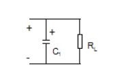
4) Capacitor filtering: Taking advantage of the characteristic that the voltage across the capacitor cannot change suddenly, the capacitor is connected in parallel with the load in the filter circuit.
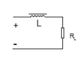
5) Inductor filtering: Taking advantage of the characteristic that the voltage at both ends of the inductor coil cannot change suddenly, the capacitor is connected in series with the load in the filter circuit.
2. Structures and Characteristics of Common Filter Circuits
|
Types
|
Circuit Forms
|
Applications
|
Advantages
|
Disadvantages
|
|
Capacitor Filter
|
|
When the load current is small.
|
1) High output voltage
2) The filtering effect is good when the current is small.
|
1) Poor load capacity
2) Large transient current
|
|
Inductor Filter
|
|
Suitable for occasions with large load changes and large load current.
|
1) Good load capacity
2) Good filtering effect on changing loads
3) Rectifier diodes are not damaged by surge currents
|
1) Big size
2) Low output voltage
|
|
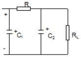
RC π-type complex filter
|
|
Suitable for situations where the load current is small and stability is required.
|
1) High output voltage
2) Good filtering effect
|
1) Small output current
2) Poor load capacity
|
|
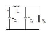
LC π-type complex filter
|
|
Suitable for occasions with small load current.
|
1) The filtering effect is good
2) Simple structure and high cost performance
3) Voltage regulation and current limitation
|
1) Small output current
2) Poor load capacity
|
|
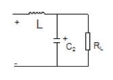
Inverted LC π-type complex filter
|
|
Suitable for occasions with large load changes and large load current
|
1) Large output current
2) Good load capacity
3) Good filtering effect
|
Big coils with high cost
|
It is necessary to note that the capacitor filter circuit is the most common and simplest filter circuit. Where a capacitor is connected in parallel to the output end of the rectifier circuit (that is, both ends of the load resistor) to form a capacitor filter circuit. The filter capacitor has a large capacity (the larger C, the smaller the low-frequency cutoff frequency, and the better the filtering effect), so electrolytic capacitors are generally used (pay attention to the positive and negative poles of the electrolytic capacitor when wiring).

 English










