Pulse Width Modulation (PWM) is a commonly used modulation technique used to convert an analog signal into a square wave signal. By adjusting the duty cycle of the square wave, precise control of the analog signal can be achieved. The principle is to express the amplitude and frequency of the analog signal as high and low level times. In a fixed period, the high-level time is called the duty cycle, which determines the amplitude of the analog signal; in addition, the period time determines the frequency of the analog signal. This technology is widely used in various fields, including power electronics, communications, automation control and motor drives.
Pulse Width Modulation Basic
PWM Tech
PWM technology controls the target device or system by changing the pulse width of the square wave signal. Further more, a common PWM signal consists of a high level and a low level, and the time ratio between the two determines the pulse width of the signal.
For PWM technology, the period remains the same, only the width of the pulse changes. So you can control the average power, voltage or current of the output signal by changing it. This method can effectively deliver high voltage or high current to the load alternately while reducing energy loss and heat generation.
Modulation Ways
Here are some common modulation methods:
1. Pulse Width Modulation
Pulse width modulation is the basic form of PWM technology, which controls the output of a target device or system by changing the pulse width of a square wave signal. The change of pulse width can be carried out according to specific rules within a certain period of time, such as linear increase or decrease, fixed duty cycle, etc. It is widely used in motor drive, lighting control, power inverter and other fields. For example, in motor driving, the speed and torque of the motor can be controlled by changing the pulse width, thereby achieving precise motor control.
2. Pulse Frequency Modulation
Pulse frequency modulation is a PWM control method that relates the output power, voltage, or current of a target device or system to the pulse frequency. By changing the pulse period (i.e. pulse frequency) of the square wave signal, the output signal can be controlled. It is commonly used in applications such as audio signal processing, digital communications, and power conversion. For example, in audio signal processing, the pitch or frequency of the audio signal can be adjusted by changing the pulse frequency.
3. Pulse Amplitude Modulation
Pulse amplitude modulation is a PWM control method that relates the output power, voltage, or current of a target device or system to the pulse amplitude. By changing the pulse amplitude of the square wave signal, the intensity and amplitude of the output signal can be adjusted. It is widely used in communication systems, audio amplification and power electronics and other fields. For example, in communication systems, the strength and amplitude of the transmitted signal can be adjusted by changing the pulse amplitude, thereby achieving long-distance data transmission.
It is the most common form, which controls the output by varying the pulse width of a square wave signal. Pulse frequency modulation (PFM) and pulse amplitude modulation (PAM) are also commonly used in reality. These methods can be used alone or in combination, and the specific application depends on the needs.
4. Phase Modulation
Phase modulation is a PWM control method that correlates the output of a target device or system with the phase change of a pulse signal. By changing the phase of the pulse signal, the output signal can be adjusted. It is commonly used in modems and radio transmissions in communication systems. For example, in a modem, the phase offset of the transmitted signal is adjusted by changing the phase to meet different transmission requirements.
5. Time Modulation
Time modulation is a PWM control method that correlates the output of a target device or system with the time changes of a pulse signal. By changing the time interval or time point of the pulse signal, the output signal can be controlled. It is widely used in automation control systems, data transmission and timing equipment. For example, in an automated control system, the movement speed and period of the actuator can be adjusted by changing the time interval of the pulse signal.
These methods play an important role in different fields and applications. And they provide the flexibility and precision to enable electronic devices and systems to meet a variety of needs and enable efficient power transfer, precise control, and reliable data transmission.
PWM Applications
Basic Fields
PWM can be used in inverter circuits and rectifier circuits to achieve conversion of direct current and alternating current. The inverter circuit converts direct current into alternating current, while the rectifier circuit converts alternating current into direct current. So they can adapt to different equipment needs.
PWM can be used to adjust the brightness of LED lights, the speed of motors, the angle of steering gear, etc. The brightness of the LED light is determined by its power-on time, and PWM can change this parameter by adjusting the duty cycle, thereby changing the brightness; the speed of the motor is determined by its input voltage, and PWM can change this parameter by adjusting the duty cycle, thereby changing the rotation speed; the steering angle of the steering gear is determined by its input pulse signal, and PWM can change this parameter by adjusting the duty cycle, thus changing the steering angle.
PWM can also be used for the synthesis and amplification of audio signals. An audio signal is an analog signal, which can be represented by a sine wave or other waveform. PWM replaces the audio signal with a series of pulses of equal amplitude and unequal width, making it easier to be digitally processed and transmitted. For example, PWM can also be used in audio amplifiers to change the output power by adjusting the duty cycle, thereby changing the volume.
PWM Fan Design
1. Concept
High-power electronic equipment such as desktops and laptops use fans to dissipate heat from the system. The most common fan is a PWM fan, using brushless DC motor, which is an armature winding, while the rotor is a permanent magnet pole, and it is also equipped with a rotor position sensor (usually a Hall element), an inverter (usually composed of power electronic devices) and commutation control device (usually an integrated circuit with integrated Hall element). Compared with brushed DC motors, this kind of motor has no brushes and mechanical commutator, and the stator and rotor are "reverse-mounted", PWM can be easily used to regulate the speed of the motor.
There are three types of PWM fans in computers:
1) 2-wire: Two 12v power supply wires, the fan works at the highest speed.
2) 3-wire: Two 12v power supply wires, the fan works at the highest speed. A typical cable outputs a speed measurement signal when the motor is working and provides speed feedback.
3) 4-wire: Two 12v power supply wires, the fan works at the highest speed. A typical cable outputs a speed measurement signal when the motor is working and provides speed feedback. When the motor is working, a PWM control signal line inputs the PWM control signal to control the fan speed (usually a square wave with a variable duty cycle. And the higher the duty cycle, the higher the motor speed).
Simple judgment method: the black is connected to the negative pole of 12v voltage, and the red is connected to the positive pole of 12v voltage. There is no unified standard for the color of the speed measuring line and PWM line. You need to judge according to the following method: connect the motor in 12V and let it works at full speed, use the voltage range of the multimeter measure the voltage of the remaining two wires relative to the black wire respectively. Then you can see the wire with voltage measured is the speed measuring wire, and the other one is the PWM wire.
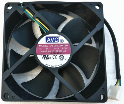
Figure 1: PWM Fan (4-wire)
2. Circuit Design
This PWM speed controller is essentially a square wave generator with adjustable duty cycle and frequency composed of a 555 timer. The computer switching power supply provides +12v voltage through the power interface (the yellow line in the switching power supply is +12v, the black line is GND), VR1 is the square wave duty cycle adjustment potentiometer, VR2 is the square wave frequency adjustment potentiometer, and the PWM fan has typical interface connection (the pin definitions of fans may be different and need to be judged based on actual conditions).
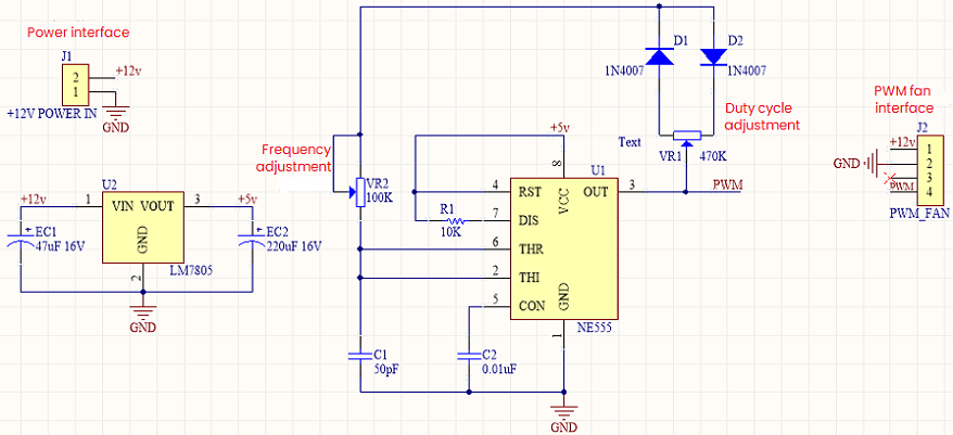
Figure 2: Schematic Diagram of a Square Wave Generator with Adjustable Duty Cycle and Frequency.
Table 1: C1 Frequency Selection
|
C1 (Capacitor)
|
Adjustable Frequency Range
|
|
10pF
|
95-180KHz
|
|
100pF
|
14.43-20.37KHz
|
|
1nF
|
1.92-2.73KHz
|
|
10nF
|
201-286Hz
|
|
100nF
|
20-28Hz
|
|
300nF
|
6.7-9.5Hz
|
|
470nF
|
4.29-6.11Hz
|
|
1uF
|
2.17-2.87Hz
|
|
2uF
|
1.1-1.5Hz
|
Table 2: Component Lists
|
Comment
|
Designator
|
Footprint
|
LibRer
|
Quantity
|
|
50pF
|
C1
|
0201C
|
CAP
|
1
|
|
0.01uF
|
C2
|
0201V
|
CAP
|
1
|
|
1N4007
|
D1, D2
|
DO-15
|
DIODE
|
2
|
|
47uF 16V
|
EC1
|
DIP-EC1, 5X4X8
|
DIP_ECAP
|
1
|
|
220uF 16V
|
EC2
|
DIP-EC1, 5X4X8
|
DIP_ECAP
|
1
|
|
+12V POWER IN
|
J1
|
Pin HDR1×2/2.54mm-S
|
Pin HDR1×2
|
1
|
|
PWM_FAN
|
J2
|
Pin HDR1×4/2.54mm-S
|
Pin HDR1×4
|
1
|
|
10K
|
R1
|
0201R
|
RES
|
1
|
|
NE555
|
U1
|
SOP8
|
NE555
|
1
|
|
LM7805
|
U2
|
TO220A
|
LM7805
|
1
|
|
470K
|
VR1
|
3296W
|
RESVR
|
1
|
|
100K
|
VR2
|
3296W
|
RESVR
|
1
|

 English










