TP4056 Li-ion Battery Charging Module
What Is TP4056?
TP4056 is a Li-ion battery charger with constant current/voltage. Its SOP8/MSOP8 package with heat sink on the bottom and low external component count make the TP4056 ideal for portable applications. And TP4056 can work with USB power supply and adapter power supply.
Due to the internal P-MOS architecture and anti-reverse charging circuit, no external isolation diode is required. Its thermal feedback automatically adjusts charge current to limit chip temperature during high-power operation or high ambient temperature conditions. And the charging voltage is fixed at 4.2V, while the charging current can be set externally through a resistor. In addition, when the charging current drops to 1/10 of the set value after reaching the final float voltage, the TP4056 will automatically terminate the charging cycle.
When the AC adapter or USB power is removed, the TP4056 automatically enters a low current state, reducing battery leakage current to less than 2uA. The TP4056 can also be placed in shutdown mode when power is available, reducing the supply current to 55uA. Other features of the TP4056 include battery temperature detection, undervoltage lockout, automatic recharge and two LED pins status to indicate the end of charge.
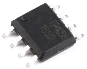
TP4056 Pinout
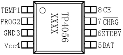
Figure 2: TP4056 Pin Configuration
TEMP 1: Battery temperature detection input terminal.
Connect the TEMP pin to the output of the battery's NTC sensor. If the voltage of the TEMP pin is less than 45% of the input voltage or greater than 80% of the input voltage, it means that the battery temperature is too low or too high, and charging is suspended. If TEMP is directly connected to GND, the battery temperature detection function is canceled and other charging functions are normal.
PROG 2: Constant current charging current setting and charging current monitoring terminal.
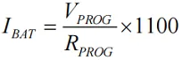
Charging current can be programmed by connecting an external resistor from the PROG pin to ground. During the precharge phase, the voltage of this pin is modulated at 0.1V; at the constant current charging phase, the voltage of this pin is fixed at 1V. In all modes of charging state, measuring the voltage of this pin can estimate the charging current according to the following formula:
GND 3: Power ground.
Vcc 4: Input voltage (positive terminal).
The voltage of this pin comes from the working power supply of the internal circuit. When the voltage difference between Vcc and the BAT pin is less than 30mV, TP4056 will enter the low-power shutdown mode, and the current of the BAT pin is less than 2uA.
BAT 5: Battery connecting terminal.
Connect the positive terminal of the battery to this pin. When the chip is disabled or in sleep mode, the leakage current of the BAT pin is less than 2uA. And the BAT pin provides charging current and a limited voltage of 4.2V to the battery.
STDBY 6: Battery charging completion indicator terminal.
When the battery charging is completed, STDBY is pulled to low level by the internal switch, indicating that the charging is completed. Otherwise, the STDBY pin will be in a high impedance state.
CHRG 7: Charging status indication terminal of open-drain output.
When charges the battery, the CHRG pin is pulled to low level by the internal switch, indicating that charging is in progress; otherwise, the pin is in a high impedance state.
CE 8: Chip enable input terminal.
A high input level will put the TP4056 in a normal working state, while a low input level will put the TP4056 in a disabled charging state. The CE pin can be driven by TTL levels or CMOS levels.
Main Features
(1) Programmable charging current up to 1000mA.
(2) No MOSFET, sense resistor or isolation diode required.
(3) A complete linear charger for single-cell lithium-ion batteries in SOP packaging.
(4) Constant current/voltage operation with thermal regulation that maximizes charging rate without risk of overheating.
(5) 4.2V preset charging voltage with an accuracy of ±1%.
(6) Charging current monitor output for battery power detection.
(7) Automatic recharging.
(8) Dual output of charging status, no battery and fault status display.
(9) C/10 charging terminated.
(10) The power supply current in standby mode is 55uA.
(11) 2.9V trickle charging.
(12) Soft start limits the inrush current.
(13) Battery temperature monitoring function.
(14) Adopt 8-pin SOP-PP/MSOP-PP package.
TP4056 Internal Structure
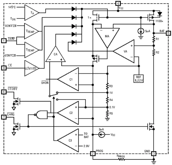
Figure 3: TP4056 Internal Structure
Working Principle
TP4056 contains two open-drain output status indication output terminals, the charging status indication terminal CHRG and the battery fault status indication output terminal STDBY. The power management circuit inside the chip automatically reduces the charging current when the junction temperature of the chip exceeds 145°C. This function allows users to maximize the use of the chip's power processing capabilities without worrying about overheating of the chip and damaging the chip or external components. In this way, you do not need to consider the worst case when designing the charging current, but just design based on typical situations. Because in the worst case, TP4056 will automatically reduce the charging current.
When the input voltage is greater than the power supply low voltage detection threshold and the chip enable input terminal is connected to high level, TP4056 starts to charge the battery, and the CHRG pin outputs low level, indicating that charging is in progress. If the battery voltage is lower than 3V, the charger uses a small current to precharge the battery. When the battery voltage exceeds 3V, the charger uses constant current mode to charge the battery, and the charging current is determined by the resistor RPROG between the PROG pin and GND. If the battery voltage approaches 4.2V, the charging current gradually decreases and TP4056 enters constant voltage charging mode. When the charging current decreases to the charging end threshold, the charging cycle ends, the CHRG terminal outputs a high impedance state, and the STDBY terminal outputs a low potential.
The charge end threshold is 10% of the constant current charging current. When the battery voltage drops below the recharge threshold, a new charging cycle automatically begins. The high-precision voltage reference source, error amplifier and resistor divider network inside the chip ensure that the accuracy of the battery terminal modulation voltage is within 1%, meeting the requirements of lithium-ion batteries and lithium polymer batteries. When the input voltage loses power or the input voltage is lower than the battery voltage, the charger enters a low-power sleep mode, and the current consumed by the battery is less than 3uA, thereby increasing the standby time. If the enable input terminal CE is connected to low level, the charger stops charging.
The charging current is set using a resistor connected from the PROG pin to ground. The setting resistor and charging current are calculated using the following formula: Determine the resistor resistance based on the required charging current:
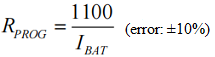
In the application, the RPROG of appropriate size can be selected according to the needs. The relationship between RPROG and charging current can be determined by referring to the following table:
|
RPROG (k)
|
IBAT (mA)
|
|
30
|
50
|
|
20
|
70
|
|
10
|
130
|
|
5
|
250
|
|
4
|
300
|
|
3
|
400
|
|
2
|
580
|
|
1.6
|
690
|
|
1.4
|
780
|
|
1.2
|
900
|
|
1.1
|
1000
|
TP4056 Typical Circuits
1) Suitable for applications that require battery temperature detection function, such as battery temperature abnormality indication and charging status indication:
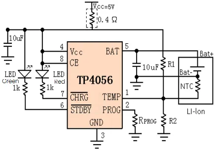
Figure 4: Battery Temperature Detection Function Circuit
2) Suitable for applications that require charging status indication and do not require battery temperature monitoring function:
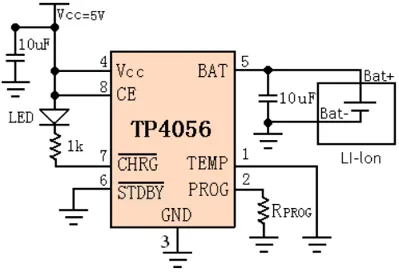
Figure 5: Charging Status Indication Circuit Example 1
3) Suitable for applications that require charging status indication and do not require battery temperature monitoring function.
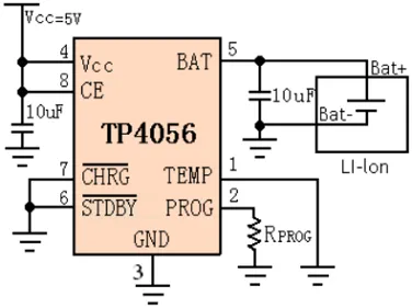
Figure 6: Charging Status Indication Circuit Example 2
4) Suitable for simultaneous use of USB interface and wall adapter charging.
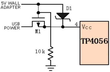
Figure 7: USB Interface for Charging
5) The charging status is indicated by a red LED, the charging end status is indicated by a green LED, and the heat dissipation power resistor is added.
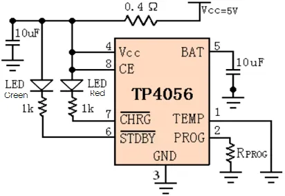
Figure 8: Charging Status Indication with Two LEDs
Conclusion
TP4056 is a complete single-cell lithium-ion battery charger using a constant current/voltage. It has battery temperature detection, under-voltage lockout and automatic recharge, and can be suitable for USB power supply and adapter power supply.

 English










