Transistor Pin Identification
1. Use Digital Multimeter
Use the digital multimeter to detect the conduction voltage drop of the two PN junctions. In fact, a transistor can be thought of as two diodes connected. For example:
1) The base of the PNP tube is the common point of the cathode of the two diodes, as shown in the figure below.
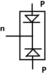
Figure 1: PNP Transistor
2) The base of the NPN tube is the common point of the anode of the two diodes, as shown in the figure below.
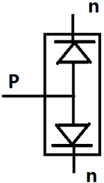
Figure 2: NPN Transistor
In this case, you can make a good judgment and it will be easy to identify the pins.
Step 1: Determine the base
Use the red test lead to touch a certain pole, and the black test lead to the other two poles respectively until the voltage drop of the two groups is measured to be about 0.3V (0.7V). Then one end of the red test lead is the base, and the tube is NPN.
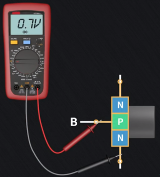
Figure 3: NPN Transistor Pin Measurement Using Multimeter (B $ E)
Use the black test lead to touch one of the poles, and the red test lead to the other two poles respectively until the voltage drop of the two groups is measured to be about 0.3V (or 0.7V). Then the section of the black test lead is the base, and the tube is PNP.
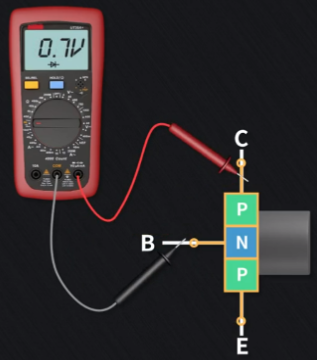
Figure 4: PNP Transistor Pin Measurement Using Multimeter
Step 2: Define the emitter and collector
After determining the base, compare the forward voltage drop between the base and the other two stages. Then the one with the larger forward voltage drop is the emitter, and the smaller one is the collector.
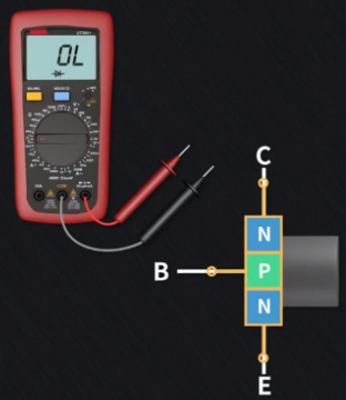
Figure 5: NPN Transistor Pin Measurement Using Multimeter ( E & C)
2. Check the Datasheet
According to the model identification to identify the pins of the transistor, as shown in the figure below, the model number of this transistor is BD136. You can search the BD136 datasheet on the Internet, and the pins will be clearly marked on it.
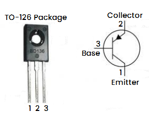
Figure 6: BD136 Transistor
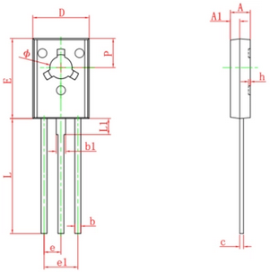
Figure 7: BD136 Pinout
3. Identify the Pins According to the Appearance
Type 1: Plastic package transistors
1) The S-1 (S-1A, S-1B) type has a semicircular bottom surface. When identifying, turn the pins down and the cutout face toward you. At this time, the pins of the transistor from left to right are e, b, c.
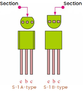
Figure 8: S-1 Transistor Pin Identification
2) Type S-2 has a block shape with a cut corner on the top surface. When identifying, turn the pins down and the cut corners toward you. At this time, the pins of the transistor are e, b, and c from left to right.
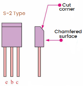
Figure 9: S-2 Transistor Pin Identification
3) The S-4 type pin identification is special. When identifying, turn the pin upward and the round surface toward you. At this time, the pins of the transistor are e, b, and c from left to right.
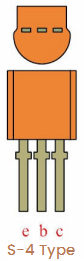
Figure 10: S-4 Transistor Pin Identification
4) There is a triangular hole in the middle of the S-5 transistor. When identifying, turn the pins down and the side with the model number facing you. At this time, from left to right, they are b, c, and e.
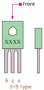
Figure 11: S-5 Transistor Pin Identification
5) Type S-6A, S-6B, S-7 and S-8 generally have heat dissipation surfaces. When identifying, turn the pins down and the side with the model number facing you, the order is b, c, e from left to right.
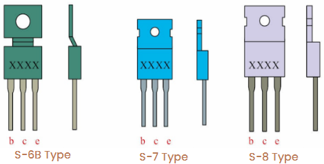
Figure 12: S-6 S-7 S-8 Transistor Pin Identification
Type 2: Metal package transistors
There is a protruding positioning pin on the shell of the B-type transistor. Turn the pin upward, starting from the positioning pin and going clockwise from the positioning pin to e, b, c, d, among which pin d is the pin of the shell.
The three pins of C-type and D-type transistors are in the shape of an isosceles triangle. With the pins facing up, the two pins at the bottom of the triangle are e and c, and the top is b.
The F-type transistor has only two pins. Place the pins upward as shown in the following figure. The upper pin is the e pole, the lower pin is the b pole, and the tube case is the collector.

Figure 13: B C D F Transistor Pin Identification
4. Use A Pointer Multimeter
(1) First, rotate the pointer to the "Rx100" or "Rx1K" position, connect the black test lead to a certain pin, and measure the other two pins with the red test lead.
* If the resistances measured are very small during the measurement, the transistor is an NPN transistor, and the electrode connected to the black test lead is the base (B) .
* If the resistance values measured are very large in the secondary measurement, the transistor is a PNP transistor, and the electrode connected to the black test lead is the base (B) .
* If during the measurement, one resistance value measured is larger and the other is smaller, then the electrode connected to the black test pen is not the base (B). At this time, the black pen should be changed to another pin for testing until the base to be found.
(2) After determining the base, rotate the multimeter function to the "Rx10K" position (use the 9V or 15V battery in the meter) to identify the collector and emitter of the NPN and PNP transistors.
* For NPN transistors, when measuring, connect the red and black test leads to the two pins outside the base respectively, at first, contact the base and the black test lead, and observe the deflection of the pointer; then exchange the red and black test leads and then measure again. Comparing these two measurements, the one with the largest pointer deflection shows that the black test lead is connected to the collector and the red test lead is connected to the emitter.
* For PNP transistors, when measuring, connect the red and black test leads to the two pins except the base, at first, contact the base with the red test lead, and observe the deflection of the pointer; then exchange the red and black test leads and observe the pointer deflection. During the measurement, when the pointer deflection is large, the black test lead is connected to the emitter and the red test lead is connected to the collector.
How to Measure the Quality of A Transistor?
Common phenomena after transistor damaged:
(1) B-E junction is short circuited and open circuited (breakdown).
(2) C-E junction is short circuited and open circuited (breakdown).
(3) C-B junction is short circuited (breakdown).
Generally speaking, when the C-E junction breaks down and is short-circuited, most of the C-B junction also breaks down and is short-circuited.
1. Detect the quality of PNP transistors
The detecting methods are as follows:
1) First remove the transistor from the circuit board, and then clean the pins of the transistor.
2) Use the "Rx1K" block of the multimeter to measure the reverse resistance and forward resistance of the collector junction and the reverse resistance and forward resistance of the emitter junction.
3) Compare the forward and reverse resistances of the collector junction and emitter junction. If the reverse resistance is less than the forward resistance, and their forward resistances are equal, then the PNP transistor is normal.
The black test lead is connected to the base of the transistor, and the red test lead is connected to the collector, to measure the reverse resistance. And then exchange the red and black test leads to measure the forward resistance of the collector junction.
2. Detect the quality of NPN transistors
The detecting methods are as follows:
1) First remove the transistor from the circuit board, and then clean the pins.
2) Use the "Rx1K" block of the multimeter to measure the reverse resistances and forward resistances of the collector junction and the emitter junction.
3) Compare the measured forward and reverse resistances. If the reverse resistances are greater than the forward resistances, and their forward resistances are equal, then the NPN transistor is normal.
In addition, as shown in the figure below, the multimeter has no reading, so it can be judged that the transistor is broken.
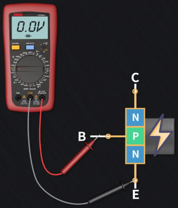
Figure 14: Detect the Quality of NPN Transistor

 English










