A relay is a device used to respond to an input signal and provide a connection between two or more devices. It can be used to control AC-powered devices, such as lights, fans, or other household appliances. Since Arduino is a low-voltage device and cannot directly control high-voltage equipment, a relay module can be used to enable Arduino to control the relay. Typically, relays are very useful when you want to control a circuit with a low-power signal. Relays used with microcontrollers are often used to control both high-voltage and low-voltage devices.
Basic Info
What is Relay?
1. Basic Meaning
A relay is an electrically operated switch that allows a low-power electrical signal to control a high-power electrical circuit. It consists of an electromagnet and a set of contacts that operate a switch. When a small voltage is applied to the relay's coil, the electromagnet becomes magnetized, which in turn attracts a metal armature. This movement either closes or opens the contacts, depending on the design of the relay, thereby allowing or stopping the flow of electricity in the controlled circuit.
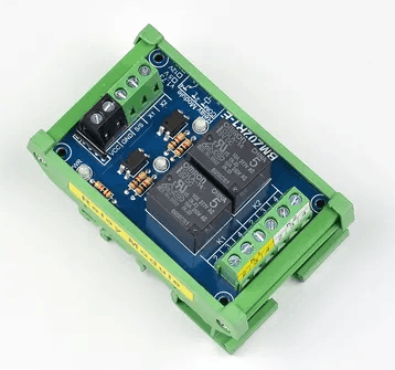
2. Key Components
Coil: The wire wrapped around a core that generates a magnetic field when energized.
Armature: A movable lever that moves in response to the magnetic field created by the coil.
Contacts: These are the conductive parts that make or break the connection in the circuit. Contacts can be normally open (NO) or normally closed (NC).
Spring: A component that returns the armature to its original position when the coil is de-energized.
3. Applications of Relays
Automotive: Used in various automotive circuits for lights, motors, and sensors.
Home Appliances: Control devices like thermostats, washing machines, and ovens.
Industrial Automation: Used in control systems to manage motors, pumps, and other heavy machinery.
Protective Circuits: Can be used as safety devices to disconnect circuits in overload or fault conditions.
Relays are essential components in both simple and complex electronic systems, allowing for remote control and automation of electrical devices.
What is Arduino Uno?
The Arduino Uno is a microcontroller board based on the ATmega328P (datasheet). It is one of the most popular and widely used Arduino boards. The board is equipped with sets of digital and analog input/output (I/O) pins that may be interfaced to various expansion boards (shields) and other circuits. The Uno is programmed using the Arduino programming language (based on Wiring) and the Arduino development environment (IDE).
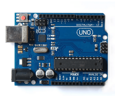
Here are some key features of the Arduino Uno:
Microcontroller: ATmega328P
Digital I/O Pins: 14 (of which 6 provide PWM (Pulse Width Modulation) output)
Analog Input Pins: 6
DC Current per I/O Pin: 40 mA
DC Current for 3.3V Pin: 50 mA
Flash Memory: 32 KB (ATmega328P) of which 0.5 KB used by bootloader
SRAM: 2 KB
EEPROM: 1 KB
Clock Speed: 16 MHz
Operating Voltage: 5V
Input Voltage (recommended): 7-12V
Input Voltage (limits): 6-20V
Length: 68.6 mm
Width: 53.3 mm
Weight: 25g
The Uno uses an ATmega16U2 (or ATmega8U2 in older versions) as a USB-to-serial converter, which allows it to communicate with the computer via a USB cable. This chip also allows the Uno to appear as a generic keyboard and mouse, in addition to a virtual serial port.
The Arduino Uno is an open-source platform, which means that its hardware designs are freely available for use and modification. This has led to a large community of users and developers who have created a vast ecosystem of libraries, code examples, and compatible hardware, making it an accessible platform for beginners and professionals alike for a wide range of electronics projects. In short, it is used in various applications including robotics, home automation, sensors, and DIY projects, making it a favorite among hobbyists and educators.
How to Connect Relay Module to Arduino?
In reality, a relay is a switch that operates electromagnetically. This electromagnet is triggered by a low voltage, such as 5V from a microcontroller, which pulls the relay contacts to connect or disconnect a high-voltage circuit. In practice, standard relay modules are powered by 5V, making them suitable for use with Arduino. Similarly, there are other types of relay modules that operate on 3.3V, which are ideal for different microcontrollers like the ESP8266 or ESP32. So, how are relays and Arduino connected?
Interfaces
A relay module generally has 6 interfaces and a high/low-level trigger selector. The 6 interfaces are:
1. Relay Module Interfaces:
DC+: Connect to the positive terminal of the power supply (according to the relay’s requirements, connect to 5V/9V/12V, typically to Arduino’s VCC or 5V).
DC-: Connect to the negative terminal of the power supply (typically connect to Arduino’s GND).
IN: Connect to the module’s output port (generally connected to a digital pin on Arduino, such as D2-D13).
2. Relay Output Interfaces:
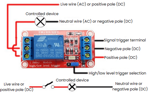
NO: Normally open contact of the relay; open before the IN input signal is received, and closed to COM after the IN input signal is received.
COM: Common interface of the relay, typically connected to the AC live wire or DC positive terminal.
NC: Normally closed contact of the relay; closed to COM before the IN input signal is received, and open after the IN input signal is received.
The high/low-level trigger selector determines the trigger mode: when set to LOW, the relay is triggered by a low level; when set to HIGH, the relay is triggered by a high level.
Arduino Relay Wiring Diagrams
Figure 3: Normally-open Contact Diagram
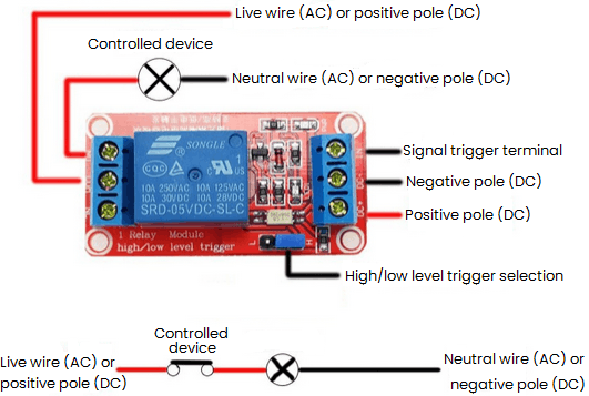
Figure 4: Normally-closed Contact Diagram
Tools Preparation
1. Arduino Uno motherboard
2. Relay module
3. Dupont wire
Hardware Connections
1) Connect the DC+ pin of the relay module to the 5V pin on the Arduino Uno board.
2) Connect the DC- pin of the relay module to the GND pin on the Arduino Uno board.
3) Connect the IN pin of the relay module to a digital pin on the Arduino Uno board (e.g., digital pin 2).
Code
Here is a simple example code for controlling the on/off state of a relay:
const int relayPin = 2; //
void setup() {
pinMode(relayPin, OUTPUT); //
}
void loop() {
digitalWrite(relayPin, HIGH); //
delay(1000); //
digitalWrite(relayPin, LOW); //
delay(1000); //
}
Testing
1) Upload the written code to the Arduino Uno board.
2) Ensure that the power connection to the relay module is properly set up.
3) After uploading the program to the Arduino board, you should hear a clicking sound, which is the noise of the normally open contacts opening and closing.
Example Explained
If you are using Arduino Relay to control a light, you can connect it as follows:
1) Set the trigger level selector to HIGH.
2) Connect the live wire in the plug to the COM terminal.
3) Connect the NO terminal to the live wire of the light.
4) Connect the DC+ to the 5V on the Arduino.
5) Connect the DC- to the GND on the Arduino.
6) Connect the IN pin to digital pin D2 on the Arduino.
7) When digitalWrite(2, HIGH) is executed, the light will turn on; when digitalWrite(2, LOW) is executed, the light will turn off.
Conclusion
Relays allow low-power microcontrollers to handle circuits that uses much higher power than what the board can handle directly. They are typically used in industrial applications to control high power circuits, but it is also used in cars, homes and other electric applications. If you want to get more details, don't miss How to Use Relays with Arduino.
You May Also Like
MCU Communication Peripherals and Protocols Explained

 English










