Thanks to solid-state circuit protection, electrical systems with DC bus voltages of 400V or higher (powered by single-phase or three-phase grid power or energy storage systems (ESS)) can enhance their reliability and resilience. When designing high-voltage solid-state battery disconnect switches, several key design decisions must be considered. Critical factors include semiconductor technology, device type, thermal packaging, device durability, and managing inductive energy during circuit interruption. In this article, we will discuss some design considerations when selecting power semiconductor technologies and defining semiconductor packaging for high-voltage, high-current battery disconnect switches, as well as the importance of characterizing the system’s parasitic inductance and overcurrent protection limits.
The advantages of wide-bandgap semiconductor technology
When selecting the best semiconductor material, several characteristics must be considered. The goal is to design a switch with the lowest possible conduction resistance, minimal off-state leakage current, high voltage blocking capability, and high power handling capacity. Figure 1 shows the characteristics of three semiconductor materials: Silicon (Si), Silicon Carbide (SiC), and Gallium Nitride (GaN). The breakdown electric field of SiC and GaN is approximately ten times that of silicon, which enables the design of devices with a drift region thickness that is one-tenth of that in equivalent silicon devices, as the drift region thickness is inversely proportional to the breakdown electric field. Additionally, the resistance of the drift region is inversely proportional to the cube of the breakdown field. This results in a nearly 1000-fold reduction in drift region resistance. In solid-state switch applications, all losses are conduction losses, and a high breakdown field is a significant advantage. Furthermore, the reduction in resistance also eliminates concerns about dynamic latch-up issues, which could otherwise be triggered by higher dV/dt transients in the parasitic NPN transistors or thyristors in silicon power MOSFETs and IGBTs.
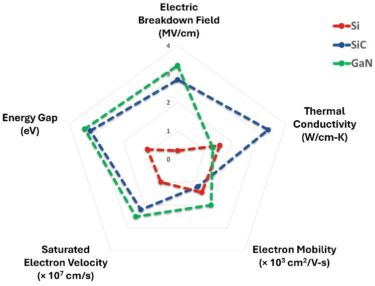
Figure 1: Characteristics of Si, SiC, and GaN Materials
Silicon Carbide (SiC) has a thermal conductivity three times that of Si and GaN, which significantly improves the chip's heat dissipation capabilities, allowing it to operate at lower temperatures and simplifying thermal design. Alternatively, for equivalent target junction temperatures, this means it can support higher operating currents. The higher thermal conductivity, combined with the high breakdown field, reduces conduction resistance, further simplifying thermal design.
SiC is a wide-bandgap (WBG) semiconductor material with a bandgap nearly three times that of silicon, allowing it to operate at higher temperatures. Semiconductors fail to perform their functions at high temperatures. The wider bandgap enables SiC to function at temperatures several hundred degrees Celsius higher than silicon due to its lower free carrier concentration. However, other factors based on current technology (such as packaging and gate oxide layer leakage) limit the device’s maximum continuous junction temperature to 175°C. Another advantage of WBG technology is its lower off-state leakage current.
Given these characteristics, SiC is the optimal semiconductor material for this application.
The differences between the following device types: IGBT, MOSFET, and JFET
The type of transistor is the next critical factor. In most cases, conduction losses are the biggest design challenge. To meet the system's thermal requirements, conduction losses must be minimized. Some systems use liquid cooling, while others may use forced air cooling or rely on natural convection. In addition to minimizing conduction losses, the voltage drop must be kept to a minimum to maximize efficiency at all operating points, including light load conditions. This is especially important for battery-powered systems. An important factor in many systems, including DC systems, is that the current is bidirectional. Transistors that typically need to combine low conduction losses, low voltage drop, and reverse conduction capability are often considered. The transistors that can be considered include IGBT, MOSFET, and JFET.
Although IGBT has conduction losses comparable to MOSFETs at peak load currents, once the load current decreases, IGBT-based solutions become inefficient. This is because the voltage drop consists of two parts: one part is almost constant and independent of the collector current; the other part is proportional to the collector current. With MOSFETs, the voltage drop is proportional to the source current. It does not have the overhead of IGBT, which allows for high efficiency at all operating points, including light load conditions. MOSFETs allow channel conduction in both the first and third quadrants, meaning current can flow in both directions through the device. MOSFETs operating in the third quadrant have the additional benefit of typically having a lower conduction resistance compared to the first quadrant. On the other hand, IGBTs conduct current only in the first quadrant and require a reverse-parallel diode to conduct reverse current. JFET is an older technology but is currently making a comeback. It can conduct in both forward and reverse directions, and like MOSFETs, its voltage drop is proportional to the drain current. The difference between JFET and MOSFET is that it is a depletion-mode device. That is, JFET is a normally-on device that requires gate biasing to suppress current flow. This presents a challenge for designers when considering system fault conditions. As a workaround, a common-source, common-gate configuration using a series of low-voltage silicon MOSFETs can be used to create a normally-off device. The addition of series silicon devices increases complexity, thus diminishing some of the advantages of JFETs in high-current applications. SiC MOSFETs are normally-off devices and combine low resistance and controllability, which are required in many systems.
Thermal packaging
SiC power modules enable advanced levels of system optimization that are difficult to achieve with parallel discrete MOSFETs. Microchip's mSiC™ modules offer a variety of configurations, voltage, and current ratings. This includes a common-source configuration, where two SiC MOSFETs are connected in series to achieve bidirectional voltage and current blocking. Each MOSFET is composed of multiple chips in parallel to achieve rated current and low conduction resistance. For unidirectional battery disconnect switches, the two MOSFETs are connected in parallel outside the power module.
To maintain a lower operating temperature for the chips, low conduction resistance and thermal resistance are required. The materials used in the module are fundamental in determining the thermal resistance from the junction to the case and its reliability. Specifically, the characteristics of chip bonding, substrate, and base plate materials are the primary factors in forming the module's thermal resistance. Choosing materials with high thermal conductivity helps minimize thermal resistance and junction temperature. In addition to thermal performance, selecting materials with closely matched coefficients of thermal expansion (CTE) can reduce thermal stress at the material interfaces and internally, thus extending the module’s lifespan. Table 1 summarizes these thermal properties. Aluminum Nitride (AlN) substrates and Copper (Cu) base plates are standard for mSiC power modules, while Silicon Nitride (Si3N4) substrates and Aluminum Silicon Carbide (AlSiC) base plates offer higher reliability. Figure 2 shows the common-source power module with standard SP3F and SP6C packaging, certified by DO-160, as well as high-reliability packages without base plates, such as BL1 and BL3.
Table 1. Thermal Properties of Chips, Substrates, and Base Plates
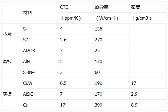
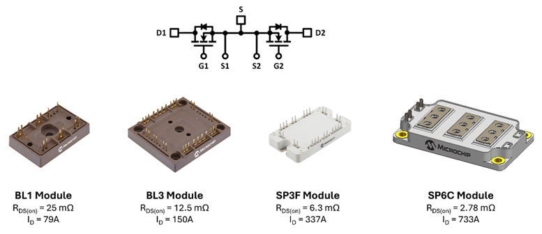
Figure 2. Microchip mSiC™ Module with Common-Source Configuration
Device Durability and System Inductance
In addition to the module's thermal performance and long-term reliability, another design consideration for circuit interrupter devices is high inductive energy. The cycle life of relays and contactors is limited. They typically specify mechanical switch cycles without load, and rarely specify electrical load switch cycles. The inductance in the system can cause arcing between contacts, leading to performance degradation when current is interrupted. Therefore, the operating conditions for the electrical cycle rating are clearly defined and significantly affect the device's lifespan. Even so, systems using contactors or relays still require upstream fuses, as contacts may weld shut under higher short-circuit currents. Solid-state battery disconnect switches are not affected by this performance degradation, contributing to a more reliable system. Nevertheless, understanding the parasitic and load inductance and capacitance of the system is crucial for managing the inductive energy during high-current interruptions.
Inductive energy is proportional to the inductance and the square of the current in the system at the time of interruption. A short circuit at the switch output terminals causes the current to rise rapidly, with a rise rate equal to the battery voltage divided by the source inductance. For example, an 800V bus voltage and a 5 μH source inductance would cause the current to increase at a rate of 160A per microsecond. A detection and response time of 5 μs would result in an additional 800A of current in the circuit. Since it is not recommended to operate SiC power modules in avalanche mode, a snubber or clamping circuit is required to absorb this inductive energy and protect the module. However, when designed to meet creepage and clearance requirements, the parasitic effects introduced by the snubber circuit further limit its effectiveness. Therefore, the switch should turn off slowly enough to limit voltage overstress and the sudden drop in current caused by internal inductance in the module. Modules with low-inductance designs help further minimize this voltage stress.
In silicon power devices, rapid interruption of high current poses the risk of triggering parasitic NPN transistors or thyristors, which can lead to uncontrolled latch-up and ultimately cause failure. In SiC devices, very fast turn-off may cause low-energy avalanche breakdowns in each chip during the turn-off process until the snubber or clamping circuit absorbs the high energy. Microchip's mSiC MOSFETs are specially designed and tested to offer Unclamped Inductive Switching (UIS) tolerance, providing additional safety margins when the performance of the snubber or clamping circuit begins to degrade. Figure 3 compares the single-trigger and repetitive UIS performance of these devices to other SiC devices on the market.
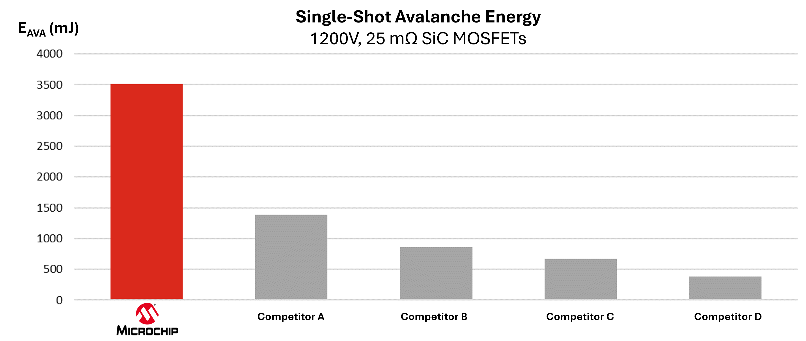
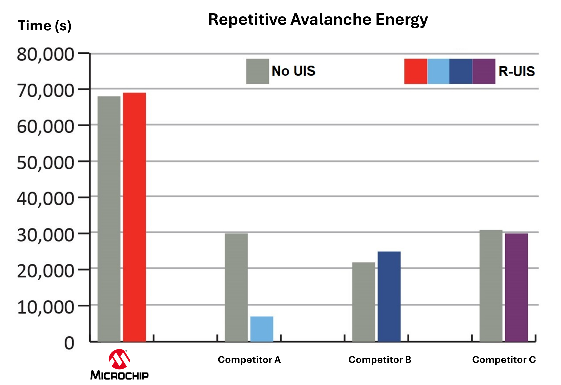
Figure 3. Single-Trigger (Left) and Repetitive (Right) Avalanche Energy Performance
While it is important to understand the short-circuit tolerance at the device level, and indeed, IGBTs have superior short-circuit capability compared to MOSFETs, practical systems face different stress conditions. Due to the inherent current-limiting characteristics of system inductance, the module is unlikely to reach its short-circuit current rating. The limiting factor is the design of the snubber or clamping circuit. To design compact and cost-effective snubber circuits, the allowable system-level peak short-circuit current will be limited to a range much lower than the module's short-circuit current rating. For example, in a 500A battery disconnect switch composed of nine chips in parallel and designed to prevent short-circuit currents from exceeding 1350A, each chip conducts 150A (assuming current is evenly distributed). This is much lower than the current during device-level short-circuit testing, where currents can exceed several hundred amps. Optimizing the voltage clamping device is a key aspect of designing a robust solid-state battery disconnect switch.
Other Design Considerations
In addition to power devices, there are several design considerations related to control electronics, including current sensing techniques, overcurrent detection and protection, and functional safety. The decision to use current sensing resistors or magnetic technologies for current detection is crucial for the design of low-parasitic inductance systems, as fast response time is essential. Whether to use hardware, software, or a combination of both for overcurrent detection is also an important decision, particularly when functional safety requirements must be met.
The above discusses some of the key aspects of selecting and designing high-voltage power devices in solid-state battery disconnect switches. The system-level advantages of solid-state disconnect switches over traditional mechanical disconnect switches primarily lie in the benefits of silicon carbide (SiC) and power semiconductor packaging. Thanks to SiC technology, devices now combine low conduction resistance and thermal resistance, achieving the low conduction losses required in many systems, while also employing materials that ensure high reliability.

 English










