As large language models revolutionise how we access data, advances in artificial intelligence (AI) are transforming how industries and society utilise data centre computing resources. We are entering an era where we can pose direct questions to AI and receive detailed answers, much like consulting a human expert rather than merely entering specific keywords into a search engine. This, of course, represents only the tip of the iceberg in terms of AI's capabilities. AI can also write code, generate images and videos, and produce meeting minutes and summaries. To realise all these AI capabilities, electricity demand is surging dramatically.
To supply such vast amounts of power and ensure AI can realise its full potential, we must reimagine the IT server rack architecture within data centres, alongside the optimal methods for acquiring and distributing electricity. This article delves into three core issues: how data centres acquire power and deliver it to the servers performing computational tasks; why transforming the power distribution architecture is essential to meet the rapidly evolving demands of AI computing and electricity; and how to achieve this transformation.
Figure 1 illustrates the projected trajectory of IT server rack-level power requirements over time. It forecasts that by 2028, a single IT rack will require 1.5MW of power – ten times the current consumption of server racks.
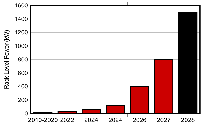
Figure 1. Rack-level power requirements
A Brief History of Evolution
To comprehend the profound transformation occurring within the power delivery networks of data centres and servers, it is necessary to first review the current architecture. Figure 2 depicts the first-generation power distribution architecture, which has dominated the server and data centre sectors since the 1990s. The top-left section of Figure 2 depicts three-phase alternating current (AC) sourced from the AC grid. This power is stepped down via transformers from approximately 13kV ‘medium voltage’ to 480V AC line voltage. An Uninterruptible Power Supply (UPS) provides buffering for this voltage.
During mains power failure, the UPS utilises local batteries and inverter functionality to sustain data centre servers until an automatic transfer switch (ATS) or static transfer switch (STS) activates backup generators to assume power supply. The 480V AC line voltage equates to 277VAC phase voltage.
Upon delivery of three-phase 277VAC power to the IT server racks, the power supply unit (PSU) performs power factor correction (PFC) and generates a stable 12V output for distribution to the server IT trays. This 12V distribution voltage serves first-generation architectures, powering various loads, voltage regulators, and other point-of-load (PoL) regulators that generate voltages to supply processors, memory, and communications integrated circuits throughout the server tray. This architecture functions effectively when total rack power ranges from approximately 10kW to 20kW. However, as demand for greater computational capability increases, so does the power required to support these computational functions.
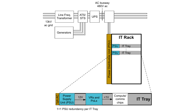
Figure 2. First-generation traditional rack server
Figure 3 illustrates the next evolution of data centre power distribution architecture. As visible in the upper left section of Figure 3, this architecture commences with the same medium-voltage input power supply. Similar to the first-generation architecture, transformers convert three-phase 13kV to 480VAC line voltage. This architecture dispenses with UPS units, instead delivering the equivalent 277VAC phase voltage directly to local PSUs within IT racks. These PSUs are no longer dedicated to individual server trays but are consolidated within unified power racks. In this context, the power rack essentially functions as a group of power supplies whose outputs collectively bear the load demands of IT equipment.
Each power rack in an N+1 configuration typically contains six PSUs to achieve redundancy. Additional power racks may be added to meet the total power demand of IT racks. These power racks output a 50VDC bus voltage, distributed to individual IT trays via high-current busbars laid along the rear of the server racks. Some second-generation units retain UPS functionality, while others remove it (as shown in Figure 3) and replace it with a local Battery Backup Unit (BBU), enabling the 50VDC bus to remain powered until mains restoration or backup generator takeover. In certain instances, capacitor racks or capacitor backup units (CBUs) help mitigate excessive voltage transients and current surges associated with any power interruption. The 50V bus within each IT tray connects to a local intermediate bus converter, generating the 12V voltage required to power the system loads within the IT tray.
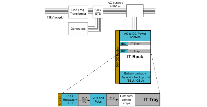
Figure 3. Second Generation — Cloud and AI Computing
The second-generation architecture enables IT rack load capacities to surpass the limitations of the first-generation architecture, achieving practical loads of up to 100kW. Once the total power requirement approaches approximately 200kW, power distribution losses increase significantly, rendering further power escalation impractical.
AI Data Centre Power Distribution
Data centre racks powering advanced AI models are projected to exceed 1MW of power by 2028. Assuming a busbar voltage of 50V, distributing this power in second-generation architectures would necessitate currents of 20,000A. Busbars capable of conveying such high currents would be excessively heavy, prohibitively expensive, and impractical. Consequently, novel AI IT server racks employ higher-voltage buses of 800VDC or ±400VDC for power distribution. This reduces the busbar's high-current requirement from 20kA to 1.25kA. Such a reduction in current magnitude helps maintain high overall power delivery efficiency while supporting the use of smaller, lower-density copper busbars. Figure 4 illustrates this architecture.
The power rack of the second-generation architecture is replaced by a side-mounted power pod, which takes three-phase 480VAC mains voltage as its input. The side-mounted power pod converts this input to 800VDC or ±400VDC bus voltage and distributes it to one or more IT server racks. The side-mounted power pod now also incorporates the BBU. Beyond enhancing power distribution efficiency, the third-generation architecture allocates more space within IT racks for computational capabilities.
In a sense, increasing the computational density within IT server racks is more critical than addressing power distribution challenges. To enable AI to function optimally, AI-based IT racks utilise hundreds of processors to rapidly process the required computational workload. These processors must be capable of communicating with each other within a high-density packaging space. Removing the majority of power conversion functions from the IT rack allows for the installation of more processors within a smaller footprint. Each IT tray within the rack now receives this 800VDC or ±400VDC bus voltage as its input. Intermediate bus converters within the tray then transform this voltage into the distribution voltage supplied to the IT tray. Depending on the chosen architecture, this distribution voltage may be 48V, 12V, or even 6V.
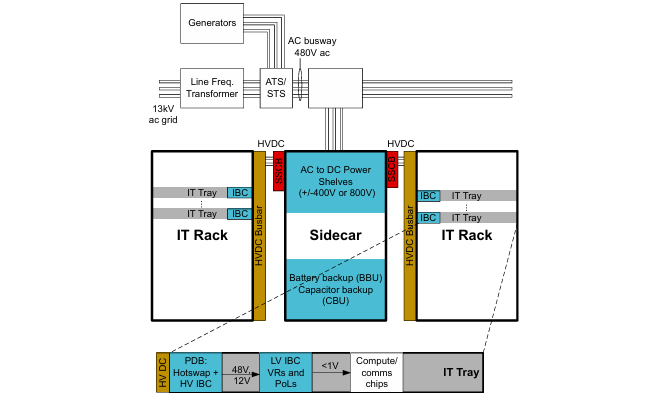
Figure 4. Third Generation — AI Computing DC Distribution Side Mounted Power Pod
How will the future unfold?
Although the third-generation architecture enhances power distribution efficiency and significantly increases computational density within IT racks, this comes at the cost of occupying more space within the data centre's IT rooms. Consequently, the next step in data centre evolution involves relocating the AC/DC power conversion function of side-mounted power enclosures from IT rooms to power distribution rooms.
Figure 5 illustrates the proposed fourth-generation architecture. Within this framework, the side-mounted power pod retains its BBU functionality, whilst the AC/DC conversion capability is relocated to the Solid-State Transformer (SST). The input voltage for the first, second, and third-generation architectures was the 13kV medium-voltage supply provided by the grid. This voltage was transformed to a three-phase 480VAC distribution bus voltage, which was then converted to a DC distribution bus voltage. The SST simultaneously replaces both the 13kV transformer and the 480VDC to 800VDC or ±400VDC power conversion stage. The SST achieves power factor correction (PFC), voltage step-down, and DC conversion within a single power conversion stage. Standby generators now connect to the medium-voltage node or feed into the SST output via AC/DC converters. This ultimately delivers a more efficient distribution network while freeing up additional computing space within IT rooms.
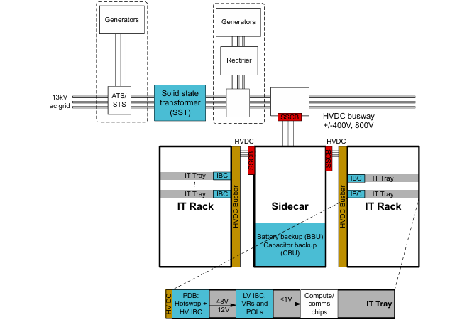
Figure 5. Fourth Generation — AI Computing SST and DC Power Distribution
The technological underpinnings for realising the vision
Each generation of power distribution architecture demands extensive precision power conversion functionality. These functions encompass PFC, 800VDC or ±400VDC DC/DC conversion, diode ORing, current sharing, hot-swap capability, protection, control, and power metering. Advanced semiconductor technology is pivotal to ensuring these functions achieve ultimate performance and efficiency. For instance:
-
Real-time microcontrollers are required to execute PFC and generate the DC bus voltage.
-
Efficient wide-bandgap semiconductor switches are required to implement topologies such as inductor-inductance-capacitor (LLC) and PFC.
-
Precise current and voltage sensing is essential for supporting power metering, control, and protection.
-
Compact, high-efficiency bias power supplies and gate drivers are needed to power the various isolated switches within the system.

 English










