A capacitor is a passive electrical component that can electrical energy in electric fields. It is very common in the circuits. So what exactly does it do? Here are 14 functions of capacitors with details and diagrams.
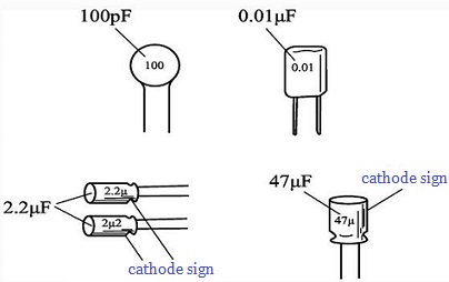
14 Applications of Capacitors with Diagrams
Coupling
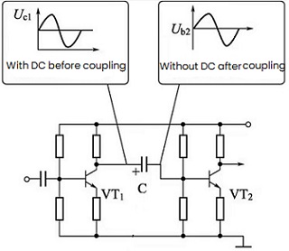
Figure 1: Coupling Capacitor Circuit
Capacitive coupling, also known as electric field coupling or electrostatic coupling, is used in electronic circuits to pass the desired AC signal and block unwanted DC components. Here coupling refers to the process of signal transmission from the first stage to the second stage, and generally refers to AC coupling when it is not specified. Because of the characteristics of capacitors, the working points of the front and back stages are not involved with each other, and the phase of the signal will be delayed. Therefore, capacitors are often used as coupling elements for small signal transmission.
The capacitor used in the coupling circuit is called a coupling capacitor. Such circuit is widely used in the RC coupling amplifier and other capacitive coupling circuits to block DC and AC. And the coupling capacitance should be selected to ensure that the input signal does not attenuate after passing through the capacitor.
Filtering
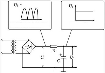
Figure 2: Filter Capacitor Circuit
Filtering is achieved by utilizing the small equivalent capacitive reactance of the capacitor to a specific frequency, which is similar to a short circuit. The characteristic of a capacitor is that it exhibits a great impedance to direct current (DC), which is equivalent to a barrier, and for alternating current (AC), the higher the frequency, the lower the impedance. Under this situation, we can filter out the AC components mixed in the DC.
The capacitor used in the filter circuit is called a filter capacitor. This capacitor circuit is used in power filtering and various filter circuits. When a capacitor is connected in a circuit, it presents an impedance to the current, thus forming a low-pass filter. That is, when the high-frequency signal in the circuit passes through, it will be filtered out due to the large impedance of the capacitor, thereby achieving the effect of filtering.
Filter capacitor is widely used in various electronic circuits, such as power filtering, audio amplifiers, radio transceivers, etc. In power supply filtering, capacitors can filter out high-frequency noise signals in the power supply, thereby ensuring the stability and reliability of the circuit. In audio amplifiers, capacitors can filter out high-frequency noise in audio signals and improve sound quality. In radio transceivers, capacitors can filter out interference signals and clutter signals to improve the quality of reception and transmission.
Decoupling
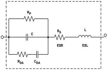
Figure 3: Decoupling Capacitor Circuit
A decoupling capacitor is a device used to isolate high frequency noise signals between two circuits. Electromagnetic interference (EMI) and radio frequency interference (RFI) are generated when signals are transmitted from one circuit to another, and they will cause errors or interference in received signals. Fortunately, system performance can be improved by using decoupling capacitors to isolate these noisy signals.
The capacitor used in the decoupling circuit is called a decoupling capacitor. This capacitor circuit is used in the DC voltage supply circuit of the multi-stage amplifier, to eliminate the harmful low-frequency crossover between each amplifier stage.
In electronic circuits, both decoupling capacitors and bypass capacitors play the role of anti-interference. The location of the capacitor is different, and the name is different. For the same circuit, the bypass capacitor takes the high-frequency noise in the input signal as the filtering object, and filters out the high-frequency clutter carried by the previous stage, and the decoupling capacitor is also used to filter out the interference of the output signal. Decoupling capacitors are used in places where no AC is required in the amplifying circuit to eliminate self-excitation and stabilize the amplifier.
High Frequency Anti Vibration
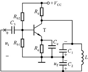
Figure 4: Self-oscillating Circuit
Oscillation is a common phenomenon in electrical circuits and it can be generated in various ways such as switch, transitions and resonance. Capacitors can eliminate oscillations by absorbing oscillation energy.
The principle of the anti-vibration capacitor is to use the characteristics of the capacitor to absorb the oscillation energy. When oscillation occurs, the capacitor will absorb part of the current, thereby reducing the magnitude of it. When the oscillation cycle ends, the damping capacitor releases the absorbed current back into the circuit, thereby canceling the effect of the oscillation on the circuit. The capacitance value of the damping capacitor is usually relatively small, generally below tens of picofarads, and the capacitor is usually connected in the circuit where the oscillation is heavy in the circuit.
In the audio negative feedback amplifier, in order to eliminate the high-frequency self-excitation that may occur in the vibration, this capacitor circuit is used to eliminate the high-frequency howling that may occur in the amplifier.
Resonance
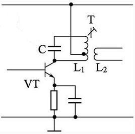
Figure 5: Resonant Capacitor Circuit
A resonant capacitor is required in both LC parallel and series resonant circuits.
Such a capacitor is often connected in parallel with an inductor. When the capacitor is discharged, the inductor starts to have a reverse kickback current, and it is charged; when the voltage of the inductor reaches the maximum, the inductor starts to discharge, and the capacitor starts to charge. This reciprocating operation is called resonance. The increase of the voltage can reach a positive maximum value, on the contrary, the minimum value can also be reached, in addition, the direction of the current will also change during this process. Further more, the inductance will generate electromagnetic waves due to continuous charging and discharging.
Bypass
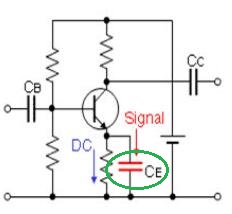
Figure 6: Bypass Capacitor Circuit
For a channel, if other signals are mixed in addition to the main signal, the branch that allows other signals to pass through and detour is the bypass, which is connected in parallel with the main channel. The bypass capacitor is a device that can bypass and filter high-frequency components in alternating current. If you need to remove a certain frequency band signals in the circuit, you can use a bypass capacitor circuit. According to the unwanted frequency, there are full-frequency (all AC signals) bypass capacitor circuits and high-frequency bypass capacitor circuits.
The main function of the bypass capacitor is to generate an AC shunt, thereby eliminating the unwanted energy that enters the susceptible area. That is, when the signal mixed with high frequency and low frequency pass through the amplifier, and the low-frequency signal is required to input to the next stage, then add a grounding capacitor at the input, in this case, the higher-frequency signal can be easily bypassed through this capacitor (because it has a small impedance to high frequency), and the low frequency signal is sent to the next stage for amplification due to the large impedance of the capacitor.
For the same circuit, the bypass capacitor takes the high-frequency noise in the input signal as the filtering object, while the decoupling capacitor takes the interference of the output signal as filtering objects.
In fact, there is no essential difference between decoupling capacitors and bypass capacitors. Capacitors in power supply systems have multiple uses. From the perspective of removing coupling noises, we can call capacitors decoupling capacitors, where from the perspective of providing an AC loop for high-frequency signals, we can call it a bypass capacitor, and the filter capacitor appears more in the circuit design of the filter.
Neutralization
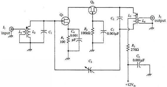
Figure 7: Amplifying Circuit Neutralization Capacitor
The neutralization capacitor is used in the intermediate frequency amplifier of the radio circuit. Its function is mainly to suppress harmful parasitic oscillations in the intermediate frequency or high frequency amplifiers. At the same time, it can improve the symmetry of the resonance curve of the intermediate frequency amplifier. In the TV high-frequency amplifier, the neutralization capacitor circuit is used to eliminate self-excitation.
There is a junction capacitance between each electrode of the triode. In the intermediate frequency and high frequency amplifiers of the radio circuit, due to the high operating frequency, the junction capacitance between the base and the collector of the triode is greatly affected. When the operating frequency of the triode is high, its capacitive reactance is also relatively small, which will cause a part of the signal current to output from the collector, and flow back to the base, causing parasitic oscillation and affecting the sound quality. To avoid this situation, a capacitive neutralization circuit is used.
Timing
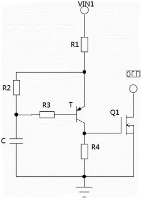
Figure 8: RC Delay Circuit
Capacitors used in RC circuits are called timing capacitors. A timing capacitor circuit is used that requires time control through capacitor charging and discharging, and the capacitor plays a role in controlling the time constant. It is best to use paper capacitors as timing parts.
Form a circuit with capacitors, resistors and other electronic components, and use the typical feature of capacitors to generate a certain time delay or pulse control signal. Its main parameters are capacity and maximum working voltage. In actual circuit design, it is necessary to select a suitable capacitor according to specific requirements. The larger the capacity of the capacitor, the longer the time delay generated under the same circuit design; and the maximum operating voltage determines the safe operating range of the capacitor in the circuit.
Integral Capacitance
In the integral circuit, because the output signal is taken from both ends of the capacitor, and the voltage across it cannot change suddenly, rises according to the law of the index, and is proportional to the integral of the charging current, so it is called integral capacitor.
It is usually used in the circuit for waveform transformation, or in the peak detector, or in the peak hold circuit, and the integration circuit is a circuit that makes the output signal proportional to the time integral value of the input signal. The simplest integrating circuit consists of a resistor R and a capacitor C. If the time constant RC is large enough, the voltage on the C can only rise slowly when an external voltage is applied. In the synchronous separation circuit for electric potential field scanning, the field synchronous signal can be taken out from the field compound synchronous signal by adopting this integral capacitance circuit.
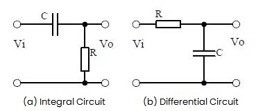
Figure 9: Integral Circuit and Differential Circuit
Differential Capacitance
Differential capacitance in physics, electronics, and electrochemistry is a measure of the voltage-dependent capacitance of a nonlinear capacitor. Capacitors used in differential circuits are called differential capacitors. In electronic circuits, the differential capacitance curve is usually used to describe the relationship between the capacitance change and the voltage. There are a few more things to keep in mind when applying differential capacitance curves. First, the shape of it may not be linear, so the nonlinearity of the curve needs to be taken into account. Second, the accuracy of it may be affected by many factors, such as measurement error, ambient temperature, etc.
In order to obtain the peak trigger signal, a differential capacitance circuit is used to obtain the peak pulse trigger signal from various (mainly rectangular pulse) signals.
Compensation
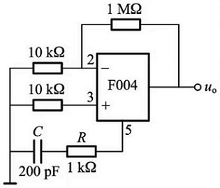
Figure 10: Compensation Capacitor Circuit
Compensation capacitors are used to counteract reactive current (increased power factor) and are basically either connected in parallel or in series. The electrical equipment of the power system will generate reactive power, and it is usually inductive. This will reduce the capacity utilization efficiency of the power supply, and it can be improved by appropriately increasing the capacitance in the system. Power capacitance compensation is also called power factor compensation (a compensation combination of voltage, current, and phase).
Applications
1) Capacitors can maintain a higher average voltage in an AC circuit, which is near peak value. It can improve the stability of increasing circuit voltage.
2) Current compensation is provided for the sudden start of large loads, and the power compensation capacitor bank can provide huge instantaneous current, which can reduce the impact on the power grid.
3) A large number of inductive loads in the circuit will cause the phase deviation of the power grid (inductive components will cause the phase of the AC current to lag, and the phase of the voltage to lead by 90 degrees), and the characteristics of the capacitor in the circuit are just opposite to those of the inductance, which acts as a compensation.
In the bass compensation circuit of the deck, the low-frequency compensation capacitor circuit is used to enhance the low-frequency signal in the playback signal.
Bootstrap
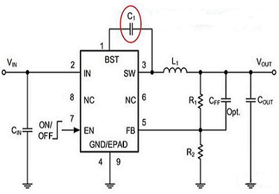
Figure 11: Bootstrap Capacitor Circuit
A bootstrap capacitor is a special circuit element that usually consists of a small capacitor and an amplifier stage. It can increase the DC bias of the circuit to a relatively high voltage in order to better drive certain electronic components. The commonly used OTL power amplifier output stage circuit uses this bootstrap capacitor circuit to slightly increase the positive half-cycle amplitude of the signal through positive feedback.
The principle of it is to use the charging and discharging process of the capacitor to amplify the signal. In the amplifier circuit, due to the existence of a DC bias voltage, if the signal output by the previous stage is only transmitted to the subsequent stage by the ordinary direct coupling method, then you will meet a problem: due to the large resistance of the latter stage, its DC component input appearing on the terminal is much larger than the signal output of the previous stage, so that the latter stage cannot directly amplify the signal of the previous. At this time, we can increase the DC bias voltage by adding a bootstrap capacitor to solve this.
Advantage:
1) Increase the input resistance of the amplifier to reduce the load on the pre-stage signal source.
2) It can provide a higher DC bias voltage and enhance the amplitude of the output signal.
3) The influence of the DC coupling capacitor on the signal is reduced, and the low frequency response of the amplifier is improved.
Bootstrap capacitors are usually suitable for amplifier circuits that require a relatively large output amplitude and low frequency, such as audio amplifiers, video amplifiers, etc.
Frequency Division
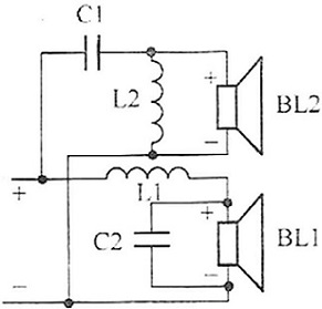
Figure 12: Speaker Frequency Division Circuit
In the speaker frequency division circuit, a frequency division capacitor circuit is used to make the high frequency speaker work in the high frequency band, the intermediate frequency speaker in the middle frequency band, and the low frequency speaker in the low frequency band.
From the working principle, the frequency divider is a filter network composed of capacitors and inductance coils. The treble channel only lets high-frequency signals pass through and blocks low-frequency signals; the bass channel is just the opposite, block high-frequency signals; the mid-range channel is a band-pass filter, the frequencies between the high frequency components and low frequency components can pass. In addition, frequency division electrolytic capacitors can also play a role in denoising. For example, in audio amplifiers and record players, such capacitors can be added to filter out unwanted noise, thereby improving sound quality.
Load Capacitance
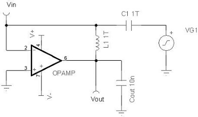
Figure 13: Capacitive Load Circuit
The load capacitance in the oscillation circuit is one of the most important values for guaranteeing the precision of a quartz crystal. It is an important point for selection and replacement of active crystal oscillators and passive crystal oscillators. The load refers to the electronic component load connected to both ends of the power supply in the circuit, including capacitive load, resistive load and inductive load. Directly connecting the two stages of the power supply without load is called a short circuit, and commonly used loads that consume power such as resistors, motors, and light bulbs. However, capacitors are components that do not dissipate power in the circuit. So what’s the meaning of load capacitance?
Simply put, the load capacitance refers to the sum of all effective capacitance values connected to the two leads of the crystal oscillator inside and outside the IC block, which can be regarded as a capacitor connected in series to the crystal oscillator in the circuit. The main function of the matching capacitor of the crystal oscillator is to match the oscillation circuit, so that the circuit is easy to start oscillation and in a reasonable excitation state, and it also has a certain fine-tuning effect on the frequency. For the MCU, the key to correctly selecting the matching capacitor of the crystal oscillator is to fine-tune the excitation state of the crystal to avoid over-excitation or under-excitation. The former makes the crystal easy to age, and causes the EMC characteristics of the oscillation circuit to deteriorate, while the latter is making the vibration not easy. So it is very important to choose the crystal matching capacitor correctly. In addition, commonly used standard values for load capacitance are 16pF, 20pF, 30pF, 50pF, and 100pF.

 English










