Abstract
The second part of this series examines the dynamic characteristics of feedback circuits in isolated forward converters, using pulse width modulation (PWM) controllers and parallel voltage regulators as reference components. The article focuses on analysing the feedback loop's response to transient load conditions and its role in maintaining output voltage stability. LTspice simulations reveal that the optocoupler's bias state and current transfer ratio (CTR) critically influence the accuracy and speed of feedback signal transmission. This paper emphasises that in high-efficiency power conversion systems, the careful selection of components and the design of compensation networks are fundamental to achieving reliable closed-loop regulation. Furthermore, the article introduces iCoupler technology—the latest alternative to traditional optocouplers—and details its advantages in terms of performance, integration, and reliability.
Introduction
In isolated power supply systems, reliable operation necessitates maintaining a stable output voltage despite varying load conditions. Feedback circuits play a pivotal role in this regulation process, dynamically adjusting the control signal transmitted to the primary-side pulse width modulation (PWM) module based on real-time output voltage deviations. This section delves into the characteristics of such feedback mechanisms, focusing on the LT3753 active clamp forward converter, LT1431 parallel regulator, and optocouplers.
The LT3753 is specifically designed for high-efficiency isolated forward converter applications, featuring active clamping control, synchronous rectification, and programmable volt-second clamping. When integrated with the LT1431 precision parallel regulator and optocoupler, it forms a robust feedback loop capable of rapid response to transient load events.
This paper employs LTspice simulations to analyse the feedback circuit's response to sudden load steps. It emphasises that the optocoupler's performance—particularly its current transfer ratio (CTR) and bias state—is decisive for constructing the feedback signal and achieving effective duty cycle modulation. Understanding these dynamic characteristics is crucial for designing power supplies that deliver stable performance across a wide range of operating conditions.
Dynamic Characteristics of Feedback Circuits
To maintain a stable output voltage, the feedback loop must dynamically respond to changes in load conditions. When the output voltage drops (typically caused by a sudden increase in load current), the parallel regulator detects this deviation and reduces its cathode current. This action decreases the current flowing through the optocoupler's light-emitting diode (LED), thereby reducing the optical output. The primary-side phototransistor receives a diminished optical signal, causing its collector current to decrease. This raises the voltage at the PWM controller's compensation (COMP) pin, signalling the controller to increase the duty cycle of the switching MOSFET or transistor. The elevated duty cycle delivers more power to the output, aiding the restoration of the output voltage to its rated value.
Conversely, when the output voltage rises (e.g., due to a sudden load reduction), the feedback mechanism activates to prevent overshoot. Upon detecting the voltage increase, the parallel regulator boosts the forward current through the optocoupler LED, enhancing the light output. This amplified light signal increases the phototransistor's conduction, thereby lowering the COMP pin voltage. The PWM controller interprets this voltage drop as a signal to reduce the duty cycle, thereby decreasing the energy delivered to the output. This corrective action helps rapidly counteract voltage spikes, maintaining stable regulation of the output voltage.
The effectiveness of this dynamic regulation depends on the optocoupler's ability to rapidly and linearly translate changes in LED current into a proportional response from the phototransistor. Ideally, the LED current waveform should exhibit abrupt changes synchronised with load steps, while the phototransistor current must track these changes. The delay time and amplitude of this tracking are determined by the CTR and the internal response time of the optocoupler. If the optocoupler responds slowly or the CTR is low, the feedback signal may exhibit lag or attenuation, leading to poor transient response manifested as overshoot, undershoot, or prolonged settling time.
Furthermore, if the LED current is excessively low, the phototransistor may fail to conduct sufficiently; conversely, an excessively high current may cause the device to enter a non-linear operating region. Both scenarios distort the feedback signal, not only compromising regulation performance but potentially destabilising the control loop. Consequently, to ensure sustained stable operation of the power supply across the full load and input voltage transient range, meticulous configuration of the optocoupler bias and judicious design of the compensation network are imperative.
Transient Load Response Analysis of the LT3753 Isolated Forward Converter
The LT3753 is a high-performance current-mode PWM controller supporting a wide input voltage range from 8.5V to 100V. It is suitable for applications requiring isolated, high-efficiency power conversion, such as telecommunications, industrial power systems, and automotive electronics.
A key feature of the LT3753 is its active clamp control, which efficiently recovers energy from transformer leakage inductance while reducing voltage stress on the primary-side switching MOSFET. This enhances the efficiency and reliability of high-density power supply designs. Furthermore, the LT3753 supports synchronous rectification, providing control signals to the secondary-side MOSFET to minimise conduction losses and improve overall power conversion efficiency.
The LT3753 incorporates a programmable volt-second clamp function, permitting duty cycles exceeding 50% to increase transformer utilisation and support higher output power. Operating at switching frequencies from 100kHz to 500kHz, it can synchronise with an external clock for noise management and system coordination. Additional features include programmable soft-start, hiccup-mode short-circuit protection, and hysteretic under-voltage lockout (UVLO)/over-voltage lockout (OVLO) thresholds for robust fault handling.
The LT1431, also featured in this simulation example design, is a precision adjustable parallel regulator incorporating an internal reference voltage up to 5V for output voltage control. The LT1431 features high accuracy (0.4% initial tolerance), low output impedance, and fast response, making it well-suited for voltage regulation and feedback control in power supplies. With a sink current capability of up to 100mA, the LT1431 effectively drives optocouplers in isolated systems.
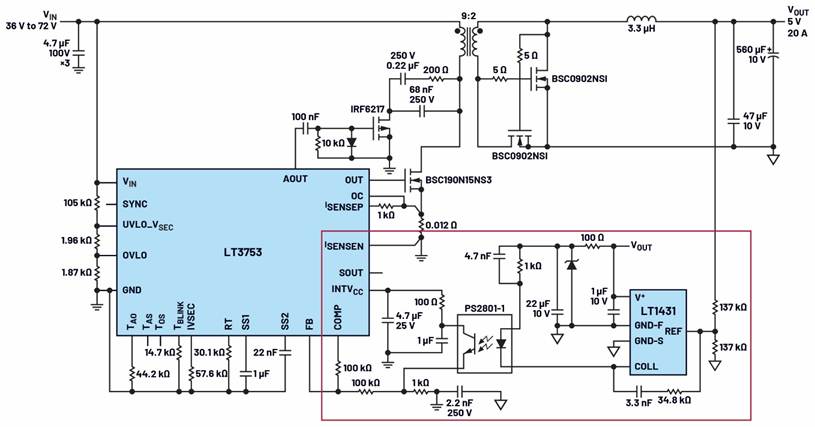
Figure 1. Connection method between the parallel voltage regulator and optocoupler in an isolated forward converter.
Based on the circuit connection configuration of the parallel voltage regulator and optocoupler shown in Figure 1, the following analysis examines LTspice simulation results for the LT3753/LT1431 demonstration circuit (an 80W active clamp asynchronous forward converter for Power over Ethernet (PoE)) under transient load conditions.
As illustrated in Figure 2, when the output current abruptly steps from 0A to 1.5A (i.e., encountering a transient load), the power supply exhibits a dynamic response. The sudden surge in load demand temporarily disturbs the system's steady state, manifesting as a voltage dip at the output terminals. This dip arises because the system initially operates under no-load conditions, requiring minimal energy transfer to maintain the output voltage. Consequently, the energy stored in the magnetic components and output capacitor proves insufficient to immediately satisfy the heightened current demand.
This transient condition disrupts steady-state operation, triggering the system's feedback control mechanism. The feedback circuit continuously monitors the output voltage, promptly detecting deviations from its nominal value. Upon detecting a voltage dip, the feedback circuit generates a correction signal and transmits it to the primary-side PWM controller.
Upon receiving the correction signal, the PWM controller dynamically adjusts the duty cycle of the switching waveform. Specifically, it increases the conduction time of the primary-side switching transistor, thereby extending the conduction period. This adjustment enhances the energy transferred through the transformer's magnetic coupling during each switching cycle. The increased energy transfer compensates for the elevated load current, facilitating the restoration of the output voltage to its regulated value.
Following the system's transition to the new load condition, the output voltage stabilises, demonstrating effective closed-loop regulation. Waveform analysis indicates that the optocoupler bias plays a critical role in maintaining loop integrity. For optimal performance, the internal LED within the optocoupler must be driven by sufficient forward current to ensure linear optical response; simultaneously, the phototransistor must operate within its active region to accurately modulate the feedback signal.
Inadequate bias (e.g., incorrect selection of series resistor on the LED side) significantly alters the CTR; this CTR serves as the key metric for evaluating signal coupling efficiency between the LED and phototransistor. A reduced CTR weakens the feedback signal, leading to insufficient response from the PWM controller to voltage deviations; conversely, an excessively high CTR may induce overcompensation, causing system instability. These effects are particularly pronounced during transient events, when the system must rapidly respond to load changes. Insufficient bias causes correction delays, voltage overshoot/undershoot, and reduced loop bandwidth.
Observed waveforms further demonstrate that precise component selection and bias design within the feedback path are paramount. Design considerations must carefully evaluate parameters such as LED forward voltage, CTR tolerance, phototransistor collector current, and compensation network design to ensure robust transient response, stable voltage regulation, and reliable system performance across a wide operating range. In isolated power supply applications, appropriate optocoupler bias not only enhances loop accuracy but also contributes to improved electromagnetic interference (EMI) immunity and long-term reliability.
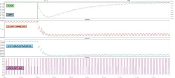
Figure 2. LTspice simulation waveforms for the LT3753 and LT1431 during instantaneous load transients.
iCoupler Isolators and Optocouplers: A Paradigm Shift in Isolation Technology
Today, switch-mode power supply (SMPS) designs increasingly adopt iCoupler digital isolation technology as a superior alternative to traditional optocouplers, particularly for applications demanding high-speed communication, robust performance, and long-term reliability. Traditional optocouplers operate by converting electrical signals into light signals via LEDs, which are then detected by phototransistors at the receiving end. Although this approach has been widely employed for decades, it suffers from several inherent limitations. Most notably, LED ageing occurs over time, degrading signal integrity and consequently reducing reliability.
In contrast, ADI's pioneering iCoupler technology employs chip-scale microtransformers manufactured using standard CMOS processes to transmit digital signals across isolation barriers. This transformer-based design eliminates the need for optical emission and detection, delivering superior temperature stability, lower power consumption, and extended operational lifespan. Unlike optocouplers, iCoupler devices are unaffected by temperature drift or LED degradation, making them ideal for harsh environments and mission-critical systems.
Performance-wise, iCoupler devices support higher data rates, typically exceeding 100Mbps, rendering them well-suited for digital control loops in SMPS architectures, telemetry systems, and high-speed communication interfaces. Moreover, iCoupler solutions frequently integrate multiple isolated channels, DC-DC converters, and diagnostic functions within a single package, saving PCB space while simplifying design complexity.
Although optocouplers remain prevalent in analogue feedback loops due to their simplicity and low cost, they are increasingly being replaced by other technologies in digital domains demanding high precision, speed, and reliability. For instance, in the solution depicted in Figure 3, the ADP1074 integrates iCoupler isolation with a synchronous PWM controller. This not only complies with safety and regulatory standards but also incorporates advanced fault protection features, delivering a compact and highly integrated solution for isolated DC-DC converters in industrial, automotive, and telecommunications applications.
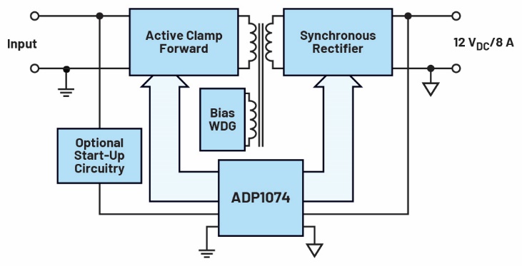
Figure 3. Isolated forward converter employing iCoupler.
The current trend in SMPS design is increasingly shifting towards iCoupler technology. This evolution not only aligns with the industry's overarching pursuit of greater integration, higher efficiency and enhanced reliability, but also enables power systems to meet the stringent standards demanded by next-generation electronic systems.
Conclusion
The isolated forward converter based on the LT3753 demonstrates effective transient load regulation through a feedback loop driven by the LT1431 parallel regulator and optocoupler. Simulation results underscore the critical importance of precise optocoupler bias and CTR in ensuring rapid and accurate duty cycle modulation. Improper bias can distort the feedback signal, leading to voltage correction delays or instability, particularly during load transients. In contrast, isolation technologies such as iCoupler offer superior bandwidth and reliability, making them ideal for high-speed or digital feedback systems. Furthermore, designing robust feedback loops requires careful consideration of component behaviour under real-world conditions, such as temperature drift and ageing. Whether employing the LT3753 or other controllers, the principles discussed herein provide a solid foundation for achieving stable, sensitive, and high-performance power regulation.
In summary, prevent feedback loops from “dropping the ball” by correctly biasing optocouplers and adopting innovative design strategies.

 English










