An electronic comparator is a circuit that compares an analog voltage signal to a reference voltage. Its main function is to compare the magnitude of two or more input signals and output the result as high level or low level. Here the output state can be used to represent the difference between input signals, or to detect and control signal changes. The two inputs of the comparator are analog signals, and the output is a binary signal 0 or 1. And when the difference between the input voltages increases or decreases and the positive and negative signs remain unchanged, the output remains constant. In general, comparators have the features of fast response, high accuracy, low power consumption, and low noise.
Comparator Circuit Basic
In a general circuit, one input signal is sent to the comparator, and the other signal is used as a reference value for comparison. If the voltage of the input signal is greater than the reference value, the comparator outputs a high level; if the voltage of the input signal is less than the reference value, it outputs a low level. Comparators are commonly used in analog signal processing, digital signal processing, power management, and sensor applications. And in digital logic design, comparators are also widely used in the design of operational amplifiers and power controllers.
Usually the comparator circuit has two input terminals IN+ and IN-. One of the input terminals can be selected as the reference point for comparison. When the voltage of the other input terminal is less than the reference voltage, the comparator outputs a low level, otherwise it outputs a high level. As shown below briefly explain with pictures.
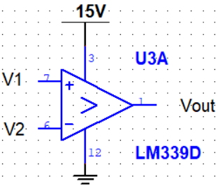
Figure 1: LM339 Voltage Comparator
Select the negative input terminal as the reference. When the positive input terminal V1 is greater than V2, Vout outputs a high level; when V1 is less than V2, Vout outputs a low level. So what are the high and low levels of the output? At this point we need to understand the circuit structure of the comparator output. Let’s first look at the internal circuit block diagram of the comparator:
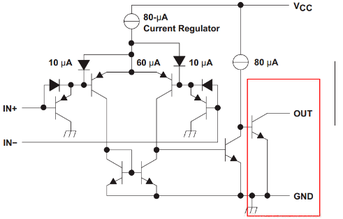
Figure 2: Comparator Internal Circuit Block Diagram
It can be seen from the block diagram that the output end of the comparator is an OC output (open collector). Speaking of OC output, you can know how to determine the high and low levels mentioned earlier. Here the OC output is floating and needs to connect with pull-up resistor: as can be seen from the picture, the high-level voltage is equal to the VCC value of the pull-up resistor, and the low-level voltage is equal to ground (0V).
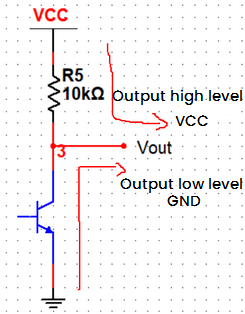
Figure 3: Comparator Output
The appropriate pull-up voltage VCC can be selected according to the output high-level voltage range. If 5V needs to be output, the output terminal will be pulled up to 5V, and the low level is determined by the ground of the comparator, which involves the power supply is signal or dual. The low-level voltage is equal to the negative power supply voltage of the comparator.
Single power supply:
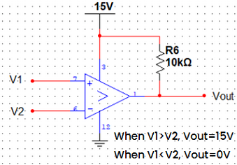
Figure 4: Signal Power Supply
Dual power supply:
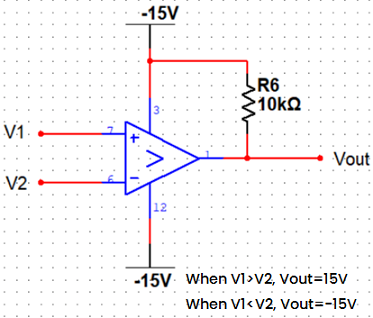
Figure 5: Dual Power Supply
It can also be seen from this application that when you do not need to output negative voltage, choose a single power supply, and if you need to output negative voltage, choose dual power supply.
Note:
1) Select the power supply according to whether the output requires negative voltage.
2) When the positive input terminal voltage is greater than the negative input terminal voltage, the comparator outputs a high level.
3) When the positive input terminal voltage is less than the negative input terminal voltage, the comparator outputs low level.
Comparator Circuit Classifications
1. Voltage Comparator
Figure 6 is a voltage comparator, Uref is the reference voltage, and Uin is the input voltage. Figure 7 shows the transmission characteristics.
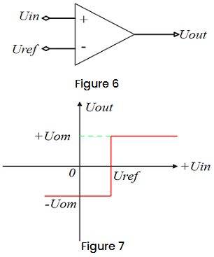
Figure: Simple Voltage Comparator
As can be seen from Figure 7, when Uin>Uref, Uout=+Uom; when Uin
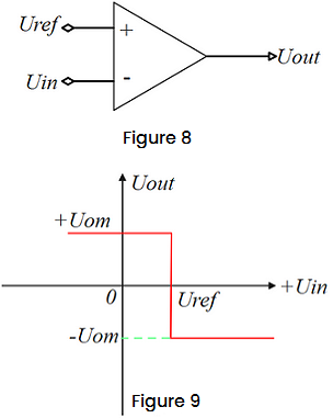
Figure: Swap Uin and Uref
As can be seen from Figure 9, when Uin>Uref, Uout=-Uom; when Uin
2. Zero-crossing Comparator
The zero-crossing comparator sets the reference voltage to Uref=0.
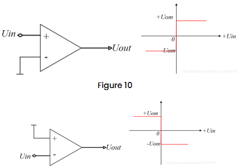
Figure 10: Zero-crossing Comparator
3. Window Comparator
The window comparator is a commonly used analog circuit. Its working principle is mainly to compare the input signal with the upper and lower thresholds, and output the corresponding high level or low level signal according to the comparison result. It has functions such as limiting, filtering and determination, and is widely used in electronic circuit design and signal processing, such as in medical instruments, robot control, audio processing, power protection and other fields.
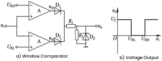
Figure 11: Window Comparator and Its Voltage Output Characteristics
The window comparator has two thresholds: an upper limit and a lower limit. The input signal is considered a valid signal only when it is between the two thresholds. If it not within threshold range, the window comparator will sound an alarm or trigger the corresponding logic circuit.
Typically a window comparator consists of multiple operational amplifiers and a voltage reference source. The operational amplifier is used to compare the magnitude relationship between the input signal and the reference voltage. When the input signal is between the reference voltages, the output signal is high level; otherwise, the output signal is low level. At the same time, by adjusting the reference voltage, the upper and lower limits of the window can be set.
4. Hysteresis Comparator
The hysteresis comparator is actually a comparator with positive feedback. Its characteristic is that when the input voltage gradually increases or decreases, it has two unequal thresholds, and its transmission characteristics have the shape of a hysteresis curve. There are two voltage thresholds of the hysteresis comparator: Uth and Utl. If two voltages need to be compared, a hysteresis comparator can be used.
Because the hysteresis comparator introduces positive feedback, and the threshold voltage is generated through this positive feedback. How did it come about? Generating positive feedback is very simple. You only need to connect the output terminal to the positive input terminal through a feedback resistor, as shown in the figure below. R6 is the feedback resistor, generally, a larger resistance resistor is selected according to the required threshold voltage.
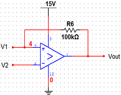
Figure 12: Hysteresis Comparator
Example: LM393 Low Power Dual Voltage Comparator
1. LM393
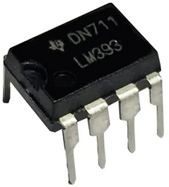
Figure 13: LM393 Low Power Dual Comparator Linear IC
Main uses: limiter, pulse generator, square wave generator, delay generator, digital logic gate circuit, multi-frequency oscillator, etc.
* Pinout diagram
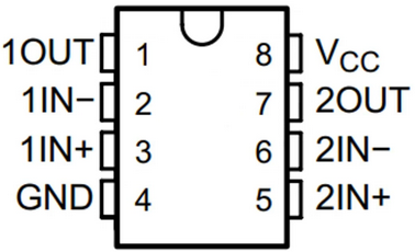
Figure 14: LM393 Pinout Diagram
* Equivalent circuit diagram
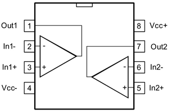
Figure 15: LM393 Equivalent Circuit Diagram
When the non-inverting terminal voltage is greater than the reverse end voltage, the output is high level; when the non-inverting terminal voltage is less than the reverse end voltage, the output is low level (please refer to the datasheet).
2. LM393 Module
There are many microcontroller switch modules made by LM393. For example: light switch, vibration switch, Hall sensor, photodiode switch, flame sensor switch, infrared obstacle avoidance module, etc.
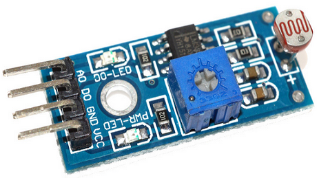
Figure 16: LM393 Voltage Comparator Module
Similar LM393 modules are all the same. The slight difference is that there are four-wire module (as shown above) and three-wire module. The difference is that one leads to the analog detection port and the other does not lead to it.
* Circuit schematic
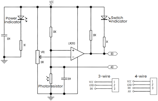
Figure 17: LM393 Module Circuit Schematic
When the light brightness is lower than the threshold, D0 outputs a high level; when the light brightness is greater than the threshold, D0 outputs a low level. For other functions, just replace the photoresistor in the figure above with related components, and then adjust the variable resistor. In addition, D0 can be directly connected to the transistor to directly control the relay.

 English










