The differential amplifier, also called as the difference amplifier, is one that outputs a signal proportional to the difference between two input signals. It uses its nonlinear characteristics and the advantages of the differential method to amplify and process differential signals. And it has the characteristics of circuit symmetry, so it can play a role in stabilizing the operating points. Differential amplifier is widely used in the input stage of direct coupling circuits and measurement circuits, and it is the basic component of the direct coupling amplifier circuit. In addition, this circuit has different effects on different input signals, for example, it has a strong inhibitory effect on common-mode signals and amplifies differential-mode signals, and its amplification capability is related to the output mode.
Differential Amplifier Basic
The Purpose of Using a Differential Amplifier
The differential amplifier has two basic input signals: differential-mode signal and common-mode signal. Due to the symmetry of the circuit, when the signals connected to the two input terminals are equal in magnitude and opposite in polarity, it is called a differential mode input signal; when the signals are equal in size and polarity, they are called common mode signals. Usually we input the signal to be amplified as a differential-mode one, and the impact of environmental factors such as temperature on the circuit is input as a common-mode signal. Therefore, the purpose is to amplify the differential-mode signal and suppress the common-mode signal.
In analog circuits, the electrical signals converted from commonly used analog quantities after passing through the sensors are relatively weak. In order to better measure these weak signals, they are generally amplified. However, when the electricity converted by them is a non-periodic signal that changes slowly, such as temperature, flow rate, liquid level and other analog quantities, such signals are generally amplified through a direct coupling amplification circuit before driving the load, but the direct coupling amplification circuit has a zero-point drift phenomenon (the input voltage is zero but the output voltage is not zero). In order to suppress the zero-point drift, transistors with the same characteristics are generally used. Such a circuit is called a differential amplifier circuit.
Typical Features
1) Strong anti-interference ability
A differential amplifier circuit amplifies two mutually opposite signals and outputs their difference, thus canceling the influence of common-mode interference signals. This enables the differential amplifier to have higher anti-interference performance against interference signals from the external environment, and can provide more stable signal output.
2) Improve signal quality
Because the differential amplifier can amplify differential signals, it can improve the dynamic range and signal-to-noise ratio (SNR) of the signal. And it also has a high amplification gain for differential signals and at the same time reduces the amplification gain of common-mode signals, thereby reducing the impact of noise and distortion. In short, it provides better signal quality in areas such as audio equipment and sensor measurements.
3) High common mode rejection ratio
An important indicator of a differential amplifier circuit is the Common Mode Rejection Ratio (CMRR). It is a measure of the differential amplifier's ability to suppress common-mode signals. Differential amplifier circuits are usually designed with higher CMRR to reduce the impact of common-mode signals on the output. This enables the differential amplifier circuit to provide a more reliable and stable signal output in the presence of common-mode interference.
Circuit Connections
1. Double-ended input, single-ended output
Due to the asymmetry of circuit parameters, the static operating point and dynamic parameters are affected. The DC path is shown in Figure 1 on the right:
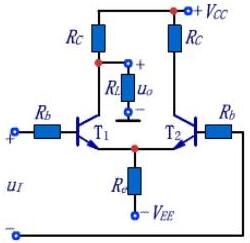
Figure 1: Double-ended input, single-ended output
When a differential-mode signal is applied, the load resistor only obtains the change in the collector potential of the T1 tube, so compared with the double-terminal output circuit, the value of the differential mode amplification factor is reduced. Figure 2 shows the equivalent circuit of a differential mode signal. Since the currents in the T1 and T2 tubes are equal in magnitude and opposite in direction, the emitter is equivalent to grounding.
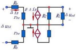
Figure 2: Equivalent Circuit of Differential-mode Signal
If the polarity of the input differential mode signal remains unchanged and the output signal is taken from the collector of the T2 tube, the output is in phase with the input. When a common mode signal is input, the input signals of the circuits on both sides are equal in size and polarity. The equivalent circuit of one side of the T1 tube related to the output voltage for the common mode signal is as follows:
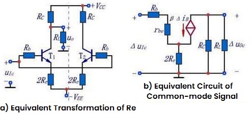
Figure 3: Equivalent Circuit of Common-mode Signal
CMRR Calculation:
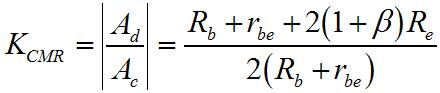
Conclusion: The larger Re, the smaller the value of Ac, the larger Kcmr, the better the performance of the circuit.
2. Single-ended input, double-ended output
In Figure (a) , for differential mode signals, the circuit transfers the emitter current to the emitter of T by connecting the emitters, so this circuit is called an emitter coupling circuit.
As shown in Figure (b), the input signal is equivalently transformed. It can be seen that the two input terminals input differential-mode signals and common-mode signals respectively.
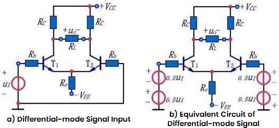
Figure 4: Single-ended input, double-ended output
It can be seen that the difference between a single-ended input circuit and a double-ended input circuit is that when the differential mode signal is input, it is accompanied by the common-mode signal input.
The output voltage:
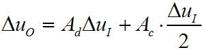
The analysis of static operating points and dynamic parameters is completely the same as that of double-ended input and double-ended output.
3. Single-ended input, single-ended output
Figure 5 on the right shows a single-ended input and single-ended output circuit. The analysis of the static operating point, differential mode gain, common mode gain, input and output resistance of this circuit is the same as that of the single-ended output circuit. The analysis of the input signal is the same as that of the single-ended input circuit.
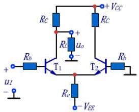
Figure 5: Single-ended input, single-ended output
Zero Drift
The basic differential amplifier circuit can suppress zero drift by taking advantage of the symmetry of the circuit. However, in practical applications, it is impossible for two tubes to be completely symmetrical, so there are limits to solely relying on circuit symmetry to suppress the zero drift of the circuit. In order to further improve the suppression effect of the differential amplifier circuit, the circuit symmetry should design well.
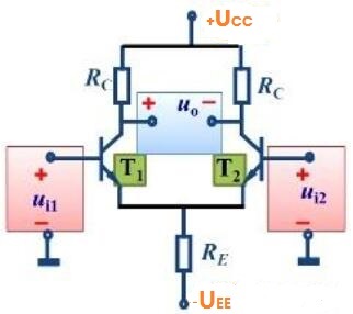
Figure 6: A Differential Amplifier Circuit
(1) The static working points of the two tubes T1 and T2 are the same. (Because of circuit symmetry, for the characteristics of the two tubes, their parameter values are equal, so their static operating points are also the same).
(2) In order to set a suitable static operating point, the circuit uses two power supplies of +UCC and -UEE. (UCC=UEE)
(3) Differential amplifier circuits often use the connection way of double-ended input and double-ended output. That is, the two input signals are connected between the bases of the two transistors and the ground, and the output signal is taken out between the collectors of the two transistors.
Differential Amplifier Applications
Differential amplifiers are used widely, especially in analog and digital circuits.
1. Amplify Signals
Differential amplifiers are used to amplify signals and are one of the most basic functions in electronic equipment. It can amplify a weak input signal to the required level, making the input signal more noticeable. The gain coefficient of it can be adjusted according to the needs of the application to meet different signal amplification requirements. For example, by differentially amplifying audio signals, the audio signals can be amplified and enhanced, thereby improving the sound quality and power output of the audio equipment.
2. Common-mode Suppression
The differential amplifier circuit has good common-mode rejection characteristics and can effectively suppress common-mode noise in the input signal, and can eliminate or reduce these common mode noises in the output signal.
3. Phase Balance
Differential amplifier circuits can amplify and process signals of different phases. In some applications, the phase information of the signal is very important. The differential amplifier circuit can maintain the relative phase relationship of the differential signal, thereby achieving balance and control of the signal phase.
4. Remove Noise
In the input signal, there are often various interference noises, such as common mode noise, power supply noise, etc. At this time, differential amplifiers can effectively remove these noise signals, making the signal more reliable and stable. That is, the differential amplifier eliminates the common-mode signal and retains the differential-mode signal, so that the noise signal no longer affects the output signal.
5. Signal Separation
Differential amplifiers can achieve signal separation, that is, the input signal is divided into two parts, differential mode and common mode, so that different signals can be processed separately.
6. Implement Digital Signals
Differential amplifier circuits can also be used in digital signal transmission and digital circuits. Digital signals include binary signals and multi-digit digital signals, which can be converted into differential mode signals through analog circuits, and then further digital signal processing is performed to achieve various calculation and control functions. So they are widely used in digital circuits.
7. Sensor Interface
Differential amplifier circuits are widely used in sensor interface circuits. Sensors usually output weak differential signals, and differential amplifier circuits can amplify these signals to appropriate amplitudes so that they can be received and analyzed by subsequent processing circuits or systems.
8. Communication
Differential amplifiers can also be used in communication systems. In communication systems, signals need to be amplified and filtered to ensure normal signal transmission, and differential amplifiers can achieve these functions, thereby helping communication systems achieve higher quality transmission.

 English










