A diode is a two-terminal electronic part that can be used as rectifiers, signal limiters, voltage regulators, switches, signal modulators, signal mixers, signal demodulators, and oscillators. Why it can have so many uses? How it plays an important role in the circuits?
Diode Basic
Types of Diodes
Point contact: small junction area, small junction allowable current, small junction capacitance, high maximum operating frequency.
Surface contact: large junction area, large junction allowable current, large junction capacitance, and low maximum operating frequency.
Planar type: the junction area can be small or large, the small one has high operating frequency, and the large one allows large current.
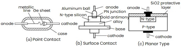
Figure 1: Types of Diodes
Volt-Ampere Characteristics
The relationship between the current of a diode and its terminal voltage, i=f (u) is called the volt-ampere characteristic. And it is a nonlinear relationship.
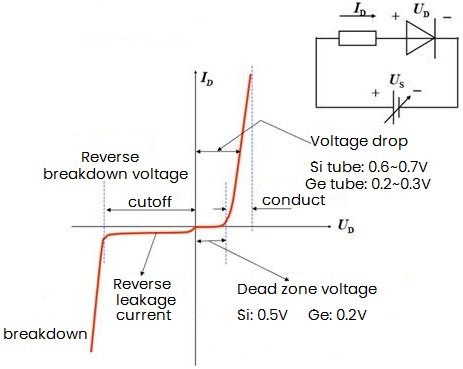
Figure 2: Volt-Ampere Characteristics
Work Area
When the applied forward voltage is very low, since the external electric field cannot overcome the resistance of the electric field in the PN junction to the majority carrier diffusion movement, the forward current is very small and almost zero. This area is called the dead zone.
When the applied forward voltage exceeds the dead zone voltage, the internal electric field is greatly weakened, the forward current increases rapidly, and the diode enters the forward conduction zone. When the voltage continues to increase, the current increases rapidly, but the voltage at the diode terminal remains unchanged, at this time, it is called the conduction voltage drop.
When a reverse voltage is applied across the diode, there will be a very small reverse saturation current (Is) formed by the minority carrier drift movement through the diode.
|
Material
|
Reverse Saturation Current
|
|
Si
|
< 1μA
|
|
Ge
|
tens of μA
|
1) It grows rapidly with the rise of temperature
2) When the reverse voltage does not exceed a certain range, the reverse current is basically constant.
When the applied reverse voltage exceeds the reverse breakdown voltage UBR, the reverse current suddenly increases, and the diode loses its unidirectional conductivity and enters the reverse breakdown region.
3) Electrical breakdown (reversible)
Avalanche breakdown (low doping concentration)
Zener breakdown (high doping concentration)
4) Thermal breakdown (irreversible)
Diode related Calculations
Diode Current Equation
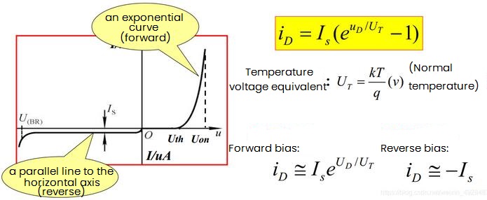
Figure 3: Diode Current Equation
V-I Characteristics are affected by temperature:
As the temperature rises, the carrier speed increases. Under the condition of constant voltage, the current increases, and the forward characteristic shifts to the left; the reverse saturation current increases, and the reverse characteristic moves down.
Diode Dynamic Resistance and Static Resistance
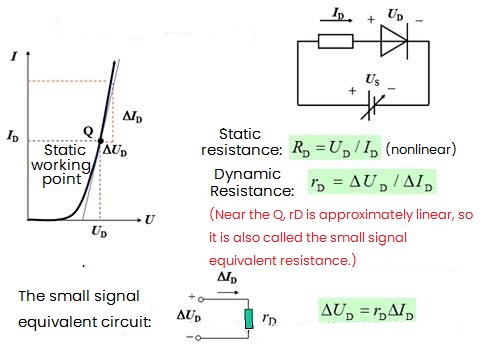
Figure 4: Diode Dynamic and Static Resistances
Maximum rectified current IF:
When the diode is used for a long time, the maximum forward average current allowed to flow through the diode.
Maximum reverse working voltage UR:
It is the reverse peak voltage given to ensure that the diode is not broken down, generally half or two-thirds of UBR.
Reverse current IR:
Refers to the reverse current of the diode when the specified working voltage is applied.
Maximum working frequency fM:
It mainly depends on the size of the capacitance of the PN junction. If the operating frequency of the diode exceeds this value, the unidirectional conductivity of the diode will become poor.
Diode Selection Principles
A germanium tube is selected when require small conduction voltage drop, and a silicon tube is selected when the reverse current is required to be small.
Select the surface contact type when require large working current, and select the point contact type when need high working frequency.
Silicon tubes are selected when high reverse breakdown voltage is required.
Choose a silicon tube when the temperature characteristic is good.
Diode Circuit Analysis
Concept
Static: When there is no input signal to the amplifying circuit, the current and voltage at each point in the circuit are DC signals, which is called DC working state or static working state.
Dynamic: When the amplifying circuit has an input signal, the voltage and current in the circuit change with the AC signal, which is called dynamic working state.
Important concept: First static and then dynamic
Symbol regulation: Everywhere in the circuit is often formed by the superposition of DC and AC quantities.
IB: DC component (capitalized symbols, capitalized subscripts)
Ib: AC component instantaneous value (lower case symbols, lower case subscripts)
iB: Total instantaneous value of current (lower case symbols, upper case subscripts)
Ib: AC rms (upper case symbols, lower case subscripts)
Ibm: AC amplitude
Diagram Analysis Method of Diode Circuit
It is to use the V-I curve of the device and the characteristic curve of the external circuit to solve the circuit problem through the method of drawing.
Steps:
(1) Static analysis. Assuming that the AC signal is 0, a DC path is obtained. Combined with the characteristic curve of the external circuit, the static operating point Q (ID, VD) is obtained.
(2) Dynamic analysis. The DC power supply is set to 0, and the AC path is obtained. Based on the static operating point, small signal analysis is performed.
As shown in the figure, the volt-ampere characteristics of the diode, the power supply VDD and the resistance R are known, the signal source νs=Vmsinωt, and the voltage vD across the diode and the current iD flowing through the diode are calculated using the graphical method.
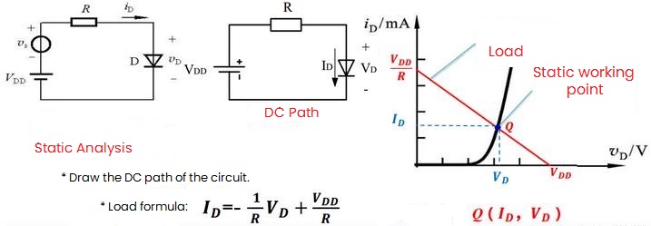
Figure 5: Static Analysis
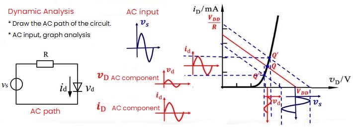
Figure 6: Dynamic Analysis
Advantages: Intuitive, helps understand the impact of circuit parameters on performance.
Disadvantages: There are drawing errors, and some parameters cannot be obtained.
Premise: The actual V-I characteristics of the device is known.
Diode Equivalent Models
Introduction
1. Linear Features
Equivalent circuit: Select the appropriate components to equivalently reflect the actual port characteristics of the device or system in a specific working area.
Modeling - Linearization - Applying linear circuit analysis methods to analyze circuits
2. Ideal Model
When the diode is forward-conducting, its forward voltage drop is zero; when the diode is reverse-cutting, it is considered that the reverse resistance is infinite and the reverse current is zero, which is called an ideal diode. At this time, the ideal diode is equivalent to an ideal switch.
This model is mainly used in circuits where the signal amplitude is much larger than the forward voltage drop of the diode, and the forward voltage drop and reverse current of the diode can be ignored.
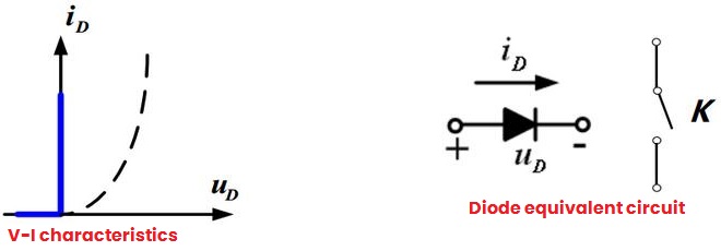
Figure 7: Diode Ideal Model
When forward biased, the tube voltage drop is 0 and the resistance is 0; when reverse biased, the resistance is infinite and the current is 0.
3. Constant Voltage Drop Model
It is considered that the forward voltage drop of the diode is constant, the reverse resistance is infinite, and the reverse current is 0. At this time, the diode can be represented by an ideal diode connected in series with a constant voltage source UD.
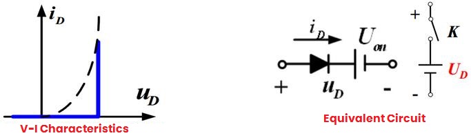
Figure 8: Constant Voltage Drop Model
When the applied forward voltage is greater than UD(on), the diode conducts and the resistance is 0.
When the applied voltage is less than UD(on), the current is 0 and the diode is off.
4. Polyline Model
Consider the conduction voltage of the diode and the dynamic resistance.
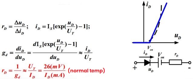
Figure 9: Polyline Model
Equivalent Model Analysis Method
Qualitative first, then quantitative
Judging the working state of the diode: on/off
|
Methods and Steps
|
|
Qualitative Analysis
|
1) Turn off the diode.
|
|
2) Analyze the polarity and magnitude of the voltage between the negative and positive access points of the diode.
|
|
Quantitative Analysis
|
3) According to the selected equivalent model, the equivalent circuit is obtained.
|
|
4) Analyze the circuit using the linear circuit method.
|
Suppose the diode circuit is shown in figure (a), VDD is 10V, 1.5V respectively, R is 10k, figure (b) is a customary drawing method. For the above two cases, find the values of iD and uD of the circuit: (It is required to apply the ideal model, constant voltage drop model and polyline model respectively.)
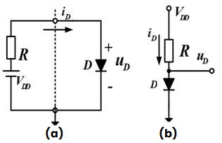
Figure 10: Diode Circuits
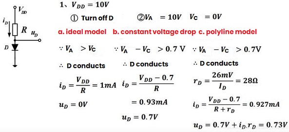
Figure 11: The Solving Process

 English










