Electrolytic capacitor is a type of special capacitors. The metal foil (aluminum or tantalum) is the positive electrode, and its oxide film (aluminum oxide or tantalum pentoxide) is the dielectric; the negative electrode is made of conductive material, electrolyte (liquid or solid) and other materials. According to their different positive electrodes, they can be divided into aluminum electrolytic capacitors and tantalum electrolytic capacitors.
Electrolytic Capacitor Basic
Advantages
1) Polymer solid electrolytic capacitors have flat capacitance-frequency characteristics in the 0.1~10MHz band. It also has temperature characteristics, for example, when the temperature changes from -55° to 105°, the capacitance only changes by -5%~+8%.
2) The rated capacity can be very large, and can easily reach tens of thousands of μf or even several f (but it cannot be compared with the electric double layer capacitance).
3) The capacitance per unit volume is very large, dozens to hundreds of times larger than other types of capacitors.
4) The price is low because the electrolytic capacitors are made of common industrial materials, such as aluminum. And the manufacturing equipment is also of ordinary industrial grade, capable of large-scale production, and is relatively low-cost.
5) Polymer solid electrolytic capacitors have the ability to withstand large ripple currents and are suitable for providing large currents in a short time in switching power supply circuits. For example, the terminal voltage drops significantly in a short period of time, so it has a strong ability to provide high-frequency current to the outside world and has good instantaneous response characteristics.
6) Aluminum electrolytic capacitors have relatively large capacitance, large series resistance, large inductive reactance, and are sensitive to temperature. It is suitable for situations where the temperature does not change much and the operating frequency is not high (not higher than 25kHz), and can be used for low-frequency filtering. In addition, aluminum electrolytic capacitors have polarity and must be installed correctly, otherwise they may explode.
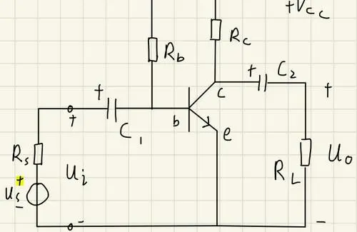
Figure 1: The Use of Electrolytic Capacitor in An Amplifier Circuit
Selection
Electrolytic capacitors are widely used in various electronic products. Their capacity and rated operating voltage range are very large, so you should pay great attention when selecting them. Next, we will summarize some rules for selecting electrolytic capacitors.
1. According to Performance
1) Voltage resistance
The withstand voltage of the electrolytic capacitor is affected by the thickness of the oxide layer. If the voltage is too high, the oxide layer will be broken down: Since the electrolyte will undergo an oxidation reaction with the anode aluminum, and the cathode will undergo a reduction reaction, eventually causing the capacitor to explode. Generally, the withstand voltage of the selected capacitor needs to be greater than 1.25 times the highest rated voltage.
2) Capacity
The capacity of the electrolytic capacitor affects the capacitor's ability to provide pulsating current. In power circuits, the capacitor capacity is required to meet the power output. Due to the large ESR of electrolytic capacitors, multiple capacitors are often required to be used in parallel, and the capacity used will be much larger than the capacity required for calculation.
3) Temperature and lifespan
The temperature of the capacitor has the most direct relationship with its lifespan, because the electrolyte of the aluminum capacitor will gradually evaporate, causing the capacitance to decrease or even fail, and the evaporation rate accelerates as the temperature increases. For every 10°C increase in temperature, the life of the electrolytic capacitor will be halved.
4) Withstand ripple current, voltage and ESR
The ripple current resistance of electrolytic capacitors is defined based on the capacitor's self-heating and heat dissipation capabilities. The larger the ESR of the capacitor, the greater the loss under the same ripple current. On the one hand, the loss affects the conversion efficiency of the circuit. On the other hand, it also increases the loss of the capacitor, causing the internal temperature of the capacitor to increase.
5) Package and size
The size of electrolytic capacitors is large. In high-power energy conversion systems, the size and heat dissipation of the capacitors need to be comprehensively considered, as well as the relationship with the overall machine structure.
2. According to Polarity
Polarized electrolytic capacitors usually play the roles of power supply filtering, decoupling, signal coupling, time constant setting, and DC isolation in power circuits or intermediate and low frequency circuits. Generally, it cannot be used in AC power circuits. When used as a filter capacitor in a DC power circuit, its anode should be connected to the positive terminal of the power supply voltage, and the cathode should be connected to the negative terminal of the power supply voltage. It cannot be connected reversely, otherwise the capacitor will be damaged.
Non-polar electrolytic capacitors are usually used in speaker crossover circuits, TV correction circuits and single-phase motor starting circuits.
Electrolytic Capacitor Polarity: How to Tell?
Generally, there are three aspects to tell the pin polarity of electrolytic capacitors:
1. Color or symbol identification on the shell.
2. Identification of capacitor pin length: The short pin is negative.
3. Recognition of circuit board symbols or circuit graphic symbols.
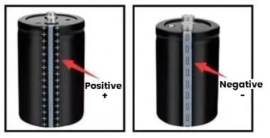
1) Screw Mount Electrolytic Capacitor
This type of capacitor has clear positive and negative electrode markings on the shell, where the positive electrode is represented by "+" and the negative electrode is represented by "-". Most of it will have "+" and "-" marks engraved next to the terminals on the cover, as shown in the figure below:
2) Snap-in Aluminum Electrolytic Capacitor
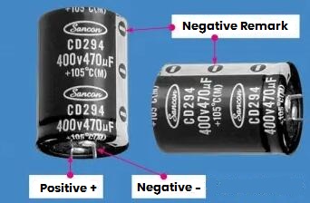
For this type of capacitor, all manufacturers currently use the "negative electrode mark", that is, the soldering pin corresponding to the "-" mark on the shell is the negative electrode. Also you can distinguish the polarity on the cover plate, for example, the negative electrode marked by "embossing", or some electrolytic capacitor manufacturers print "+" and "-" marks directly on the rivets, as shown in the figure below.
3) SMD Aluminum Electrolytic Capacitor
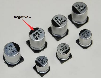
Some electrolytic capacitor shells are clearly marked with negative polarity pin marks, such as "-" symbols or black marks. Usually the end with these marks is the negative polarity pin.
4) Electrolytic Capacitor with Leads
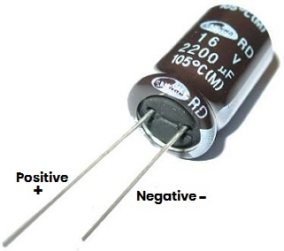
This also adopts the "negative mark", that is, the lead corresponding to the "-" mark on the casing is the negative polarity. Another method is to identify by the length of the lead, for example, the long lead is the positive pole, and the short lead is the negative pole. In addition, some electrolytic capacitors will have obvious gaps near the positive polarity pins. So it is very simple to distinguish the pin polarity of the capacitor based on these characteristics. As shown below:
5) Polarity Identification on the Circuit Board
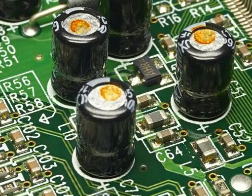
If an electrolytic capacitor is installed on a circuit board, there is usually a polarity symbol or circuit graphic symbol printed near it. So the pin polarity of the capacitor can be easily identified based on the circuit graphic symbol.
Basic Calculation Equations
1) Capacity (Farad)
Imperial: C = ( 0.224 × K · A) / TD
Metric: C = ( 0.0884 × K · A) / TD
2) Energy stored in a capacitor
1/2CV2
3) Linear charging capacity of capacitor
I = C (dV/dt)
4) Total impedance of capacitor (ohms)
Z = √ [RS2 + (XC – XL)2 ]
5) Capacitive reactance (ohms)
XC= 1/(2πfC)
6) Phase angle Ф
Ideal capacitor: leads current voltage by 90°
7) Dissipation coefficient (%)
D.F. = tanδ (loss angle)=ESR/XC= (2πfC)(ESR)
8) Quality factors
Q = cotanδ=1/DF
9) Equivalent series resistance ESR (ohms)
ESR = (DF) XC = DF/ 2πfC
10) Power consumption
Power loss = (2πfCV2 ) (DF)
11) Power factor
PF = sin δ(loss angle)–cosФ(phase angle)
12) Root mean square
rms = 0.707×Vp
13) Kilovolt-ampere KVA (kilowatt)
KVA = 2πfCV2×10-3
14) Temperature coefficient of capacitor
T.C. = [ (Ct–C25) / C25 (Tt – 25) ]×106
15) Capacity loss (%)
CD = [ (C1–C2)/C1 ]×100
16) Reliability of ceramic capacitors
L0 / Lt = (Vt / V0)X (Tt / T0)Y
17) Capacitance value when connected in series
n capacitors in series: 1/CT = 1/C1 + 1/C2 + …. + 1/Cn
Two capacitors in series: CT= C1·C2/(C1 + C2)
18) Capacitance value when connected in parallel
CT = C1 + C2 + …. + Cn
|
Explanation of symbols in formulas
|
|
K=dielectric constant
|
V=voltage
|
L=inductor inductance coefficient
|
L0=service life
|
V0=operating voltage
|
|
A=area
|
RS=series resistance
|
δ=loss angle
|
Lt=test life
|
Tt=test temperature
|
|
TD=insulation layer thickness
|
f=frequency
|
Ф=phase angle
|
Vt=test voltage
|
T0=operating temperature
|
|
X, Y = Effect index of voltage and temperature
|
Electrolytic Capacitors Alternative Rules
1. Try to choose the original model to replace.
2. Generally, the capacitance deviation of electrolytic capacitors is larger, which will not seriously affect the normal operation of the circuit, so the capacitance can be slightly larger. But this is not possible in frequency division circuits, S correction circuits, oscillation loops and delay loops. The capacitance should be as consistent as possible with the calculation requirements. In some filter networks, the capacitance of electrolytic capacitors is also required to be very accurate, and its error should be less than +0.3%~0.5%.
3. The withstand voltage requirements must be met, and the selected withstand voltage value should be equal to or greater than the original value.
4. Non-polar capacitors are generally replaced by non-polar capacitors. If not, two polar capacitors with twice the capacity can be connected in reverse series and replaced. The method is to connect the positive poles of the two polar electrolytic capacitors in a circle or connect their two negative terminals.
5. When selecting electrolytic capacitors, it is best to use high-temperature-resistant electrolytic capacitors. The maximum operating temperature of it is 105°C, when they operate at 105°C, they can guarantee a normal working time of about 2,000 hours. When using an capacitor with the maximum operating temperature of 85°C at 50°C, its lifespan can reach 22,000 hours. If a high-temperature electrolytic capacitor is used at this situation, its lifespan can reach 90,000 hours.
The last point, the material of the capacitor. When we replace some electrolytic capacitors, of course it must be close to the capacity and voltage resistance of the original one, similar electrolyte, high-voltage to low voltage, high capacity to low capacity, these are the most basic. However, when it comes to the solid capacitors, we cannot follow such rules, because the semiconductor material of solid capacitors determines that there is a lot of room for replacement with electrolysis: low ESR, high voltage resistance, and better high temperature resistance, etc. That is, solid capacitors seem to have more advantages than electrolytic capacitors.

 English










