A filter capacitor is a capacitor that removes a specific frequency or frequency range from a circuit, which used to improve the high-efficiency DC output. Since the filter circuit requires the energy storage capacitor to have a large capacitance, most filter circuits use electrolytic capacitors. So how does the electrolytic capacitor play a filtering role?
Filter Capacitor Circuits
Rectifier Circuits with Filter Capacitor
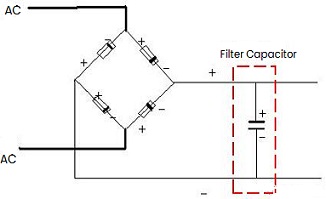
Figure 1: Filter Capacitor Circuit Example
The main function of the filter capacitor is to help reduce noise such as ripple and interference in the signal, thereby providing a smoother DC output or protecting subsequent circuits from unintentional interference. The most common one is in the rectifier circuit. When the rectified voltage is higher than the capacitor voltage, the capacitor is charged, and when it is lower than the capacitor voltage, the capacitor is discharged. In this process, the output voltage remains basically stable.
For electrolytic capacitor filtering, the capacitance must first be determined, which depends on the main operating frequency on the PCB and the harmonic frequencies that may affect the circuit. And you can refer to the relevant technical manuals. The next thing to note is that the capacitor must be connected correctly in the circuit. The positive electrode of the electrolytic capacitor is connected to the + terminal of the rectifier output circuit, and the negative electrode is connected to the - terminal of the circuit. In all circuits that need to convert AC into DC, setting up filter capacitors will make the working performance of the electronic circuit more stable, and at the same time reduce the interference of alternating pulsation ripples. In order to obtain a good filtering effect, the capacitor must discharge slowly so that the output voltage becomes smoother.
Inductor Filtering and Capacitor Filtering
Capacitors and inductors are two common components in circuits, and they play different roles in circuits. When a voltage is applied to both ends of the capacitor, the charges accumulate to form an electric field, that is, capacitor is an energy storage component. And it plays the role of filtering and voltage stabilization in the circuit. An inductor is a component that can store magnetic field energy. When current passes through a conductor coil, a magnetic field will be generated in the iron core. The energy stored in the coil can be used to generate electromagnetic induction, filter, have voltage stabilization, etc. It can be seen that both devices can be converted into each other, and the two are closely related.
The impedance of an inductor is proportional to frequency, and the impedance of a capacitor is inversely proportional to frequency. Therefore, the inductor can block the passage of high frequencies, and the capacitor can block the passage of low frequencies. Many properties of them are exactly opposite. So by properly combining the two, various frequency signals can be filtered. For example, in a rectifier circuit, connecting any one to the load in series can filter out the AC ripple.
1) Filter Capacitor
It is a voltage filter, which directly stores the pulsating voltage to smooth the output voltage, and its output voltage is high and close to the peak value of the AC voltage. Filter capacitor is suitable for small currents, and the smaller the current, the better the filtering effect.
2) Filter Inductor
It is a current filter, which smooths the output current by generating electromagnetic induction through the current, and its output voltage is low, lower than the effective value of the AC voltage. Filter capacitor is suitable for large currents, and the greater the current, the better the filtering effect.
Low Frequency and High Frequency
Under normal circumstances, the role of electrolytic capacitors is to filter out low-frequency signals in the current, and they have several orders of magnitude. Therefore, in order to be suitable for use at different frequencies, there have high-frequency capacitors and low-frequency capacitors (the high frequency here is relative).
1) Low Frequency Filter Capacitor
It is mainly used for mains power filtering or transformer rectification filtering, and its working frequency is 50Hz consistent with the mains power. In these situations, capacitors have a pulsating voltage frequency of only 100Hz, and charge & discharge times are on the order of milliseconds.
In order to obtain a smaller pulsation coefficient, the required capacitance is as high as hundreds of thousands of microfarads. Therefore, the goal of ordinary low-frequency aluminum electrolytic capacitors is to increase the capacitance. And the capacitance, loss tangent value and leakage current of the capacitor are the identification factors of capacitor working performance.
2) High Frequency Filter Capacitor
It mainly works in filtering after rectification of switching power supply, and its operating frequency is from several thousand Hz to tens of thousands Hz. Its sawtooth voltage frequency is as high as tens of thousands of hertz or even tens of megahertz.
At this time, capacitance is not the main indicator. The standard for measuring the quality of high-frequency aluminum electrolytic capacitors is the "impedance-frequency" characteristic. It is required to have a lower equivalent impedance within the operating frequency of the switching power supply, and at the same time have a good filtering effect on the high-frequency spike signals generated.
3) High Pass and Low Pass
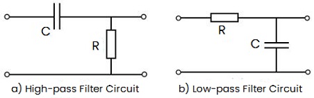
Figure 2: RC Filter Circuits
In the high-pass or low-pass filter circuits, the capacitor and the resistor are in series. With the characteristic of passing high frequency and blocking low frequency, the voltage drop generated when the high-frequency signal passes through the capacitor is very small, and the loop (high-frequency) current is relatively large. According to the series voltage division, at this time the voltage obtained by the resistor is very large, close to the input voltage. In other words, the frequency input voltage is basically equal to the resistor voltage (output voltage). In the same way, when the low-frequency voltage signal passes through the capacitor, the voltage drop is relatively large. Obviously, the voltage divided by the resistor is very small, and it can be ignored. At this time, it is equivalent to the low-frequency input voltage has no output and has been filtered out.
Effect of Power Filter Capacitor Size on Voltage
1. Principle of capacitor filter circuit
When the input pulsating voltage U is higher than the voltage across the filter capacitor, the capacitor is charged. If the opposite, the filter capacitor begins to discharge and assumes the responsibility of providing power to the load, compensating the downward input pulsating voltage. It reduces the pulsation degree of pulsation voltage (ripple coefficient). The larger the filter capacitor, the smaller the filtered output voltage ripple.
2. Is the larger capacity better?
There is no doubt that the larger the capacity, the higher the cost, but more importantly, when the filtering capacity is large to a certain extent, the benefits brought by the capacitor capacity will be less.
1) For example, if the capacity of the filter capacitor is from 10uF to 100uF, the ripple voltage improvement is 64V-22V=42V; the ripple improvement value from 100uF to 1000uF is 22V-4.24V=19.6V, and from 1000uF to 1000uF; the ripple improvement value of 4700uF is only 4.24-1.35=2.89V, as shown below:
|
Capacity Change
|
Input
|
Output
|
|
10uF →100uF
|
90uF
|
42V
|
|
100uF→1000uF
|
990uF
|
19.6V
|
|
1000uF→10000uF
|
3700uF
|
2.89V
|
It is obvious that the larger the capacity, the corresponding ripple voltage decreases. However, the larger the filter capacitor is, the less benefits can be obtained. From an economic point of view, it means diminishing marginal benefits.
2) The necessity of excessive filtering capacity. The purpose of the filter capacitor is to reduce the AC pulsating voltage (ripple coefficient), not to output a stable voltage.
3) If the capacity of the filter capacitor is too large, the charging current (ripple current) will also be larger, and excessive ripple current will cause greater damage to the circuit system. Ripple current refers to the RMS value (effective value) of the AC ripple current that the capacitor can withstand under the maximum operating temperature condition, and the specified ripple is a sine wave in the frequency range (100Hz ~ 120Hz) .
Calculation of Power Filter Capacitor
The capacitor is similar to a water tank, with one end injecting water and the other end taking out water. The capacitor charges at a certain speed. If there is one person coming to get water (one load) at this time, then the water inflow and outflow will balance each other. If there are a group of people (multiple loads) coming to get water at this time, then the charge of the capacitor will not enough. At this time, the voltage across the capacitor will fluctuate. If the capacity is larger, then the fluctuation will be smaller, and the voltage supplied to the load will be more stable (it will not jitter as the load increases). Therefore, the larger the energy storage filter capacitor is, the better, but the larger the capacitor, the more expensive it is, so the selection of the capacitor is very particular.
1. Factors affecting ripple
A very important significance of using a capacitor is to enable the load to receive a relatively stable voltage, that is, the ripple is relatively small. The ripple is the variation range of the voltage, which is mainly affected by two factors:
1) Frequency or cycle of charging voltage
The frequency of the charging voltage indicates the frequency of drawing water from the water tank, whether the water is drawn every 10s or every 5s, that is, the frequency of the charging voltage. The faster the charging frequency, the better the charging effect of the capacitor, and the smaller the ripple will be under the same conditions.
2) The size of the capacitor value
If the capacitance value is very small, the voltage (charge) in the capacitor may be gone before the next charging time, which will cause the voltage received by the load to be very unstable.
2. Capacitance calculation formula
The selection of capacitor is also related to the size of the discharge current.
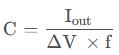
Where,
Iout refers to the magnitude of the discharge current of the capacitor, that is, the magnitude of the current of the circuit behind the capacitor.
ΔV refers to the fluctuation of the voltage flowing from the capacitor, that is, the difference between the maximum voltage and the minimum voltage of the ripple. You must first specify how large the ripple is.
F refers to the frequency of charging the capacitor.
Note: In different rectifier circuits, the frequency of charging the capacitor is different. For example, a half-wave rectifier circuit will only charge the capacitor in the positive half cycle, while a full-wave rectifier circuit will charge the capacitor in a cycle.
3. Capacitance value calculation case
It is required that the voltage fluctuation does not exceed 0.9V, f=54KHz, Iout=100mA, how to calculate the capacitance?

Note: Multiply by 10 to the 6th power to convert farads to microfarads.
Power Filter Capacitor Selection
Parameters need to be considered when using capacitor filtering:
1) ESR: equivalent series resistance
Power supply filtering and switching power supply depend on the equivalent series resistance value of the capacitor.
2) ESL: equivalent series inductance
ESL is the apparent inductance in a capacitor, which only becomes noticeable beyond certain frequencies.
3) Voltage resistance
It is generally 1.2–1.5 times higher than the maximum voltage across the capacitor. Of course, it is better to be higher, but in practice, the volume and price of the capacitor should be considered.
4) Resonant frequency
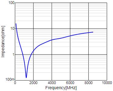
The best choice for high-frequency capacitors is at their self-resonant frequency. Large capacitors prevent surges, while small capacitors filter high-frequency interference. The smaller the capacitor, the higher the resonant frequency, and the higher the interference frequency that can be filtered. Any device can be equivalent to a series-parallel circuit of resistors, inductors, and capacitors, and there is self-resonance. The equivalent resistance is the smallest at self-resonance frequency, so the filtering effect is the best.
The lowest point of the curve represents the self-resonant frequency point, where the impedance is minimum. The following are frequency curves for impedance-frequency relations:
Figure 3: 1uf Capacitor
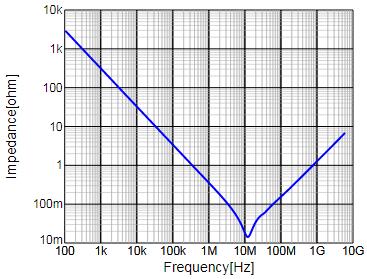
Figure 4: 1nf Capacitor
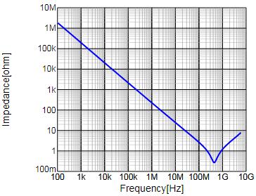
Figure 5: 10nf Capacitor
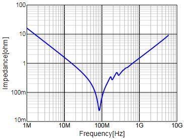
Figure 6: 100pf Capacitor
5) Size of capacitor
When designing, use 4.7uF in the front stage to filter low frequencies, and 0.1uF (104 capacitor) in the second stage to filter high frequencies.
The function of the 4.7uF capacitor is to reduce output pulsation and low-frequency interference.
The 0.1uF capacitor reduce high-frequency interference caused by instantaneous changes in load current.
Note: The above is a single experimental data, which is not suitable for all filter capacitor situations. The specific situation depends on the comprehensive consideration of other parameters.

 English










