Over the last decade, battery powered applications have become essential and require a level of protection to ensure safe use. This safety is provided by the Battery Management System (BMS). The BMS monitors the battery and possible fault conditions, prevents any hazardous situations due to the battery or its surroundings, and ensures an accurate estimation of the remaining battery capacity or the level of battery degradation.
The main structure of a BMS for a low-voltage or medium-sized battery cell usually consists of three ICs, as described below:
1. battery monitor and protector: also known as analogue front end (AFE), the battery monitor and protector provides the first level of protection as it is responsible for measuring battery voltage, current and temperature.
2. microcontroller unit (MCU): the MCU processes data from the battery monitor and protector and usually contains the second level of protection, including monitoring thresholds.
3. Fuel Gauge (FG): The Fuel Gauge is a separate IC that provides up-to-date charge (SOC), health (SOH) information and remaining runtime estimates, as well as other user-relevant battery parameters.
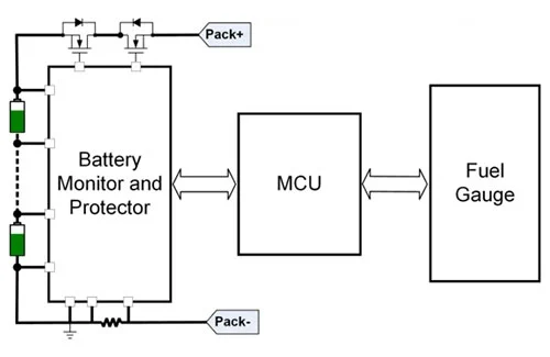
Figure 1 BMS architecture showing the key three building blocks.
Figure 1 shows the main structure of a complete BMS for low or medium voltage batteries. The fuel gauge can be a standalone IC or embedded in the MCU. The MCU is the central element of the BMS, taking information from the AFE and fuel gauge and interfacing with the rest of the system.
Although the three main components make up the BMS, the use of these components without any other considerations is not sufficient to ensure that the system meets the level of safety required in some industries. This paper will explain the role of functional safety in a non-automated battery management system and how to achieve the required level of safety.
Introduction to Functional Safety
Functional safety is a branch of overall safety that focuses on reducing the risk from hazardous events due to functional failures of electrical/electronic (E/E) systems. The aim is to ensure that the residual risk is within acceptable limits.
In recent years, the increasing use of E/E systems in different fields such as automotive, mechanical, medical, industrial and aerospace has been accompanied by an increased focus on functional safety. These changes have led to the development of different functional safety standards.
ISO 13849, entitled ‘Safety of machinery - Safety-related parts of control systems’, is a functional safety standard that focuses on the safety-related parts of control systems (SRP/CS) in mechanical fields. This is a field that encompasses a wide range of applications, from general industrial machinery to motorbikes and e-bikes. ISO 13849 defines different levels of safety as Performance Levels (PL), which range from PLA (lower safety level) to PLE (higher safety level).
The safety standard defines a precise process for risk assessment and reduction. It proposes a simplified method for determining the achieved PL based on three parameters: category, mean time to hazard failure (MTTF D) and average diagnostic coverage (DC AVG), which is calculated by averaging all the DCs associated with different safety measures applied to the system.
The category is a classification of the SRP/CS that describes its resistance to faults and its subsequent behaviour in the event of a faulty state. There are five categories (B, 1, 2, 3 and 4).
The architecture has the greatest impact on the category. The basic architecture of the SRP/CS consists of three functional blocks: inputs, logic blocks and outputs (Fig. 2). Figure 2 corresponds to the architecture proposed for Class B and Category 1, which is called the ‘single-channel’ architecture. The single-channel architecture is considered to be the most basic architecture for implementing the nominal functions of the SRP/CS, but it is not intended to be used for any diagnostic functions.

Figure 2 presents the above architecture for category B and category 1.
Classes B and 1 rely on the reliability of their components (MTTF D) to ensure the integrity of the safety function. If the component implementing the safety function fails, the safety state cannot be guaranteed because there is no diagnosis (DC AVG = 0).
For category 2, the proposed architecture is called ‘single-channel tested’. The basis of this architecture is the same as the single-channel architecture, but with an added test device block that diagnoses whether the functional channel is working correctly. If a component implementing a safe function fails, the safe function is not executed; however, if the test device diagnoses a failure, a safe state can be achieved.
For categories 3 and 4, the proposed architecture is called ‘redundant channel’, which is implemented through two independent functional channels and can diagnose problems on the other channel. If the component implementing a safety function fails, the safety function can still be executed by the other channel. The designer should select the SRP/CS category based on the target level of safety for each safety function.
Progressive implementation of functional safety
The ISO 13849 standard defines an iterative process in which the SRP/CS design is evaluated to determine the PL achieved and to check whether the level of safety is sufficient or must be improved in a new ring. The process includes three different approaches to risk reduction: risk reduction through safe design measures, risk reduction through safeguards and risk reduction through information. ISO 13849 supports risk reduction through safeguarding risks (Figure 3).
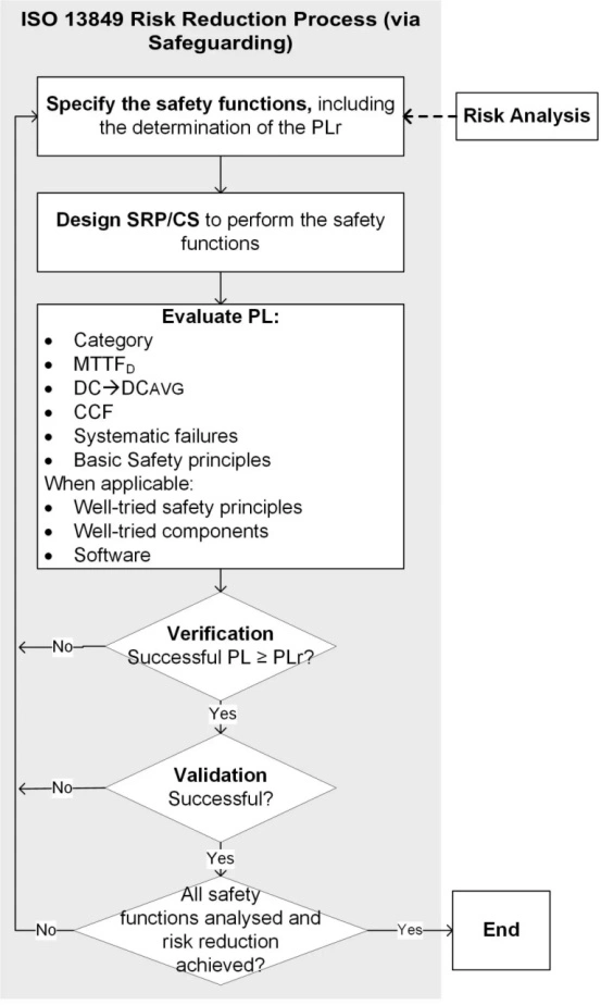
Figure 3 ISO 13849 reduces risk through assurance support.
The protection process starts by defining the safety function of the SRP/CS, and the required performance level (PLR) is defined after the function has been risk analysed. The PLR is the target PL of the SRP/CS for each safety function.
The next step consists of designing the SRP/CS for the specified security requirements.This involves considering possible architectures, implemented security measures, and finalising the design of the SRP/CS to perform the relevant security functions.
After designing the SRP/CS, the performance level of the implementation of each security function is evaluated. This is a core step in the overall protection process. To evaluate the achieved PL, define the categories and then calculate the MTTF D and DC AVG of the SRP/CS for each individual safety function .
MTTF D is calculated per channel and has three levels (Table 1).

Table 1 MTTF D, calculated for each channel, with three levels.
Table 2 shows the four levels of DC that define each diagnostic metric.
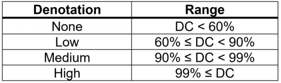
Table 2 has four levels to define the DC for each diagnostic metric.
The achievable PL can be determined using the relevant parameters (Table 3).
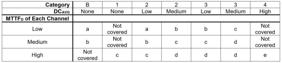
The relevant parameters in Table 3 help to determine the achievable PL.
An achievable PL can only be validated if the remaining requirements and analyses defined by the standard have been implemented in the design. these requirements must comply with the system's fault management, common cause failure (CCF) analyses, safety principles, and software development if applicable.
Once this process has been completed. the SRP/CS shall be verified by PLR as the PL achieved by the concrete safety function. if PL < PLR. the SRP p CS shall be redesigned. this process shall be reiterated for each safety function. < CS has achieved the required level of safety and validation must be performed to ensure correct behaviour through testing. If there is unexpected behaviour then the SRP CS shall be redesigned and the PL assessment process shall be restarted. If PL ≥ PLR, then SRP >
Functional safety levels based on each market
Battery-powered devices are used in a myriad of markets, each of which requires different functional safety specifications based on the level of risk to humans and/or the environment from failure. Table 4 shows the functional safety levels required for some of the major markets. Note that these levels are constantly changing and may vary depending on the design of each engineering team.

Table 4 This is based on the way the market determines the PL.
Whilst these are current performance level market expectations, electrification and certain energy storage applications may be coming to PLDs due to ongoing issues with battery powered equipment around the world.For example, poor energy applications have led to fires at Energy Storage System (ESS) facilities in the US. In the UK, over 190 people were injured and eight were killed by fires caused by e-bikes and e-driver failures.
All of these events could have been prevented with stronger, more reliable systems. The need for ever-increasing levels of safety means it is vital to have scalable solutions that can be realised at different levels of performance.
Functional Safety Design Recommendations
Taking the BMS concept of ISO 13849 as an example, MONOLITHIC POWER SYSTEMS (MPS) has developed it by combining the MCU with a battery monitor and protector consisting of the MP279X family of MP279X. As shown in Table 5, the system is orientated to achieve a PLC safety level (SFS) for a set of safety functions (SFS). The PLR determination depends on a risk analysis in which minor changes can be made as well as applications using a BMS.
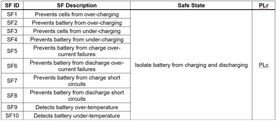
Table 5 refers to the defined safety functions of the BMS concept.
The congressman proposes to realise that the solution proposed by the PLC can comply with category 2 or category 3 (for each safety function) for certain safety functions. There is only one input block and for the others there are redundant input blocks.
Figure 4 shows how SF2 and SF4 can be implemented to prevent undercharging and charging of the battery pack. When implementing the SRP/CS, there are two logic blocks: the battery monitor and protector (logic 1) and the MCU (logic 2). These logic blocks are used to diagnose the correct functioning of the different parts of the design.
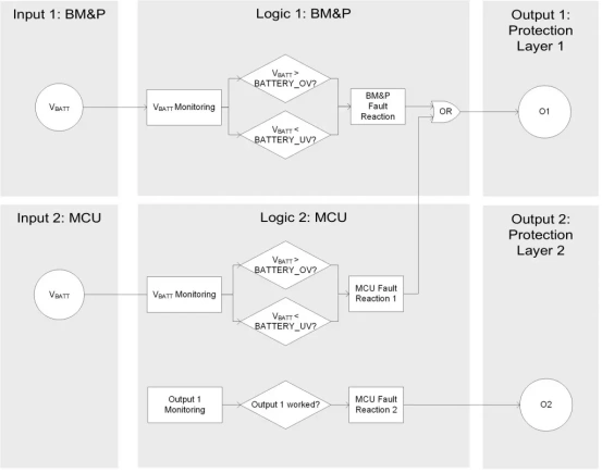
Figure 4 This is how SF2 and SF4 are realised.
The implementation of single or duplicate inputs depends on the complexity and cost in each case. To ensure that the safety features of individual inputs are PLC-compliant, other safety measures can be taken to improve diagnostics; one example is a cell voltage plausibility check to verify that the cell voltage measurement is correct.
Functional safety was once associated with automotive products, but today most modern markets require manufacturers to comply with functional safety standards. The best-known safety standard for the non-automation market is ISO 13849, a system-level standard that ensures the safety and robustness of applications.

 English










