Abstract
In system-on-chip (SoC) applications, power supply solutions utilising integrated power management ICs (PMICs) must meet a number of stringent performance criteria: not only must they deliver high output current, but they must also ensure fast load transient response with minimal ripple, whilst simultaneously offering low electromagnetic compatibility (EMC) interference, low temperature rise and low power consumption in sleep mode.
ADI’s single-chip switching regulators, which incorporate field-effect transistors (FETs), support high output currents whilst delivering low power consumption and low heat dissipation. Furthermore, they meet other key performance requirements necessary for SoC applications.
As fully integrated single-chip IC solutions, they significantly reduce PCB footprint, contributing to the miniaturisation of devices.
Introduction
Nowadays, automotive electronic systems commonly utilise electronic control units (ECUs) to electrically control and manage mechanical subsystems. Each ECU performs a specific function, whilst modern vehicles are equipped with a large number of ECUs to meet diverse control requirements. As functional integration continues to deepen, the functions of multiple ECUs are gradually being consolidated into a single unit, placing higher demands on the processing performance of System-on-Chip (SoC) devices responsible for centralised control tasks. Consequently, the power supply current required by the system has also risen sharply.
As shown in Figure 1, the SoC utilises an integrated power management IC (PMIC) to generate multiple voltage rails, supplying power to internal functional modules such as the CPU and memory. The PMIC itself is typically powered by a 3.3V supply. In automotive electronic systems, the main power source is generally a lead-acid battery with a nominal supply voltage of approximately 12V to 14V. The path supplying the 3.3V power to the PMIC is generated by a primary power IC, which must deliver a load current of 10A or more. As the PMIC has a relatively narrow permissible input voltage range, the output voltage of the primary power IC must be maintained with high precision, whilst strictly controlling voltage fluctuations caused by ripple and load disturbances.
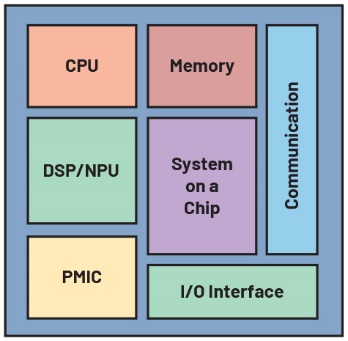
Figure 1: Schematic diagram of the SoC architecture
Key Requirements for SoC Power Supplies
When the load current requirement exceeds 10 A, a solution typically involves using a controller IC to drive an external field-effect transistor (FET). To handle high currents and address the resulting thermal management challenges, a discrete architecture comprising a controller IC paired with an external switching FET offers distinct advantages. Generally speaking, single-chip ICs with integrated FETs are ill-suited for such high-current, high-thermal-stress applications. The LT8648S, however, is a single-chip IC capable of meeting the high-current demands of SoC applications and is currently used in automotive electronic control units (ECUs) to supply power to the SoC’s internal PMIC.
Figure 2 shows the PCB layout of the controller IC and the single-chip IC evaluation board. Compared to controller ICs that require external FETs, single-chip ICs with integrated FETs can significantly reduce the PCB footprint.
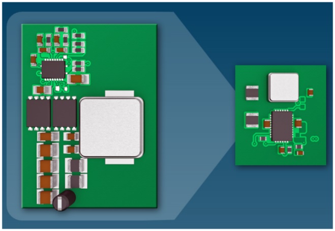
Figure 2: PCB layout of the controller IC and single-chip IC
As SoC performance continues to advance at a rapid pace, the demand for supply current has risen accordingly. The LT8648S has been successfully brought into mass production and is widely used as a PMIC power supply in automotive electronic systems; however, as load currents increase further, greater demands are placed on thermal management capabilities. To address this, ADI has introduced the LT8648SP device to meet these requirements. As shown in Figure 3a, traditional IC packaging encapsulates the silicon chip in resin, with heat primarily conducted to the PCB via exposed pads on the bottom for dissipation. In contrast, the LT8648SP exposes the silicon chip at the top of the package, as shown in Figure 3b. A heat sink can be mounted directly onto the exposed chip to achieve efficient heat dissipation. As shown in Figure 4, without a heat sink, the thermal performance of the LT8648SP is comparable to that of the LT8648S; however, when a heat sink is fitted, the temperature rise of the LT8648SP is less than half that of the LT8648S. Thanks to this improvement in performance, the LT8648SP can handle significantly higher load currents.
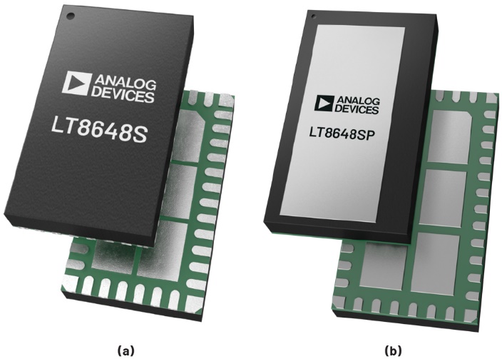
Figure 3: (a) The surface of the LT8648S; (b) The surface of the LT8648SP
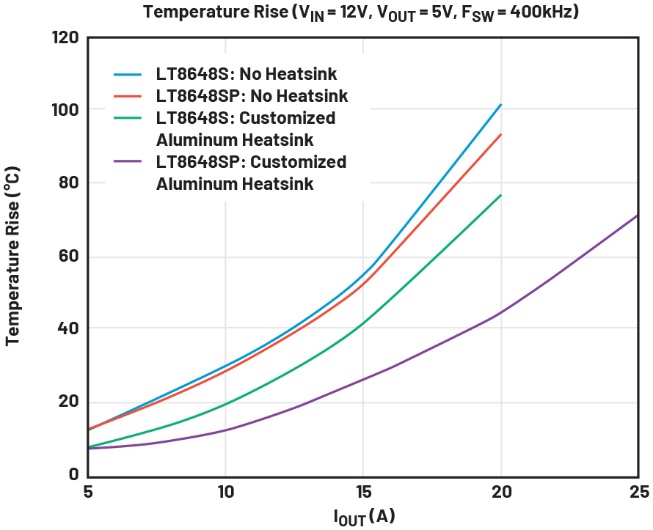
Figure 4: Comparison of temperature rise between the LT8648S and LT8648SP.
As mentioned earlier, SoCs place extremely high demands on load current. As load current continues to increase, the challenges of electromagnetic compatibility (EMC) design also grow, requiring the addition of extra filtering circuits and peripheral components, which leads to a steady rise in system complexity. The main power supply IC, which is connected directly to the battery, has a particularly significant impact on electromagnetic compatibility within the ECU and must therefore exhibit excellent radiated emissions (RE) and conducted emissions (CE) performance. The LT8648S/LT8648SP incorporate ADI’s patented Silent Switcher® 2 architecture. As shown in Figure 5, Silent Switcher technology reduces electromagnetic radiation by symmetrically arranging the input capacitors, confining electromagnetic fields to the immediate vicinity of the IC and significantly enhancing EMC performance. Silent Switcher 2 technology further optimises EMC performance by integrating the input capacitors within the package, adjacent to the silicon die, as shown in Figure 6. Consequently, the LT8648S/LT8648SP fully complies with the CISPR 25 Class 5 requirements for automotive electronics; the test results are shown in Figure 7.
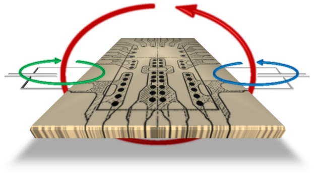
Figure 5: Structure of the Silent Switcher
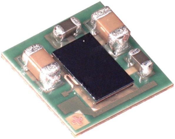
Figure 6: Internal view of the Silent Switcher 2 LT8609S
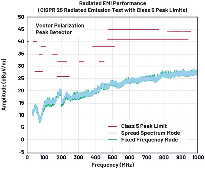
Figure 7: Radiated electromagnetic compatibility performance curve for the LT8648S

Figure 8: Load transient response between light and heavy loads
Whilst the vehicle is in motion, the processing load on the SoC changes rapidly and fluctuates significantly. As the SoC’s input current requirements also vary accordingly, the power management IC must possess excellent load transient response performance. As shown in Figure 8, even when subjected to significant load current transients, the LT8648S/LT8648SP can quickly recover to the set output voltage, with minimal voltage overshoot and undershoot. This characteristic is crucial for the PMIC supplying power to the SoC, as the latter permits only a narrow input voltage range.
When the vehicle is switched off and in standby mode, low quiescent current becomes a key metric. In standby sleep mode, the SoC periodically wakes up to perform monitoring tasks before returning to sleep; this operating mode is known as periodic wake-up. In this mode, the LT8648S/LT8648SP must supply power at extremely low power consumption. ADI’s patented Burst Mode® operating mode significantly reduces power consumption under light-load conditions. Figure 9 compares the switching waveforms and inductor currents between Burst Mode and forced continuous mode. Burst Mode® does not employ fixed-frequency switching; the switch is activated only when the output voltage falls below a set threshold, thereby reducing switching events and maintaining high efficiency under light-load conditions. When the system is in sleep mode, the synchronisation pin (SYNC) can be pulled low to enable Burst Mode®; during normal operation, the synchronisation pin is pulled high to enable forced continuous mode. The operating mode can be switched seamlessly whilst the device is running, without causing any disturbance to the output voltage.
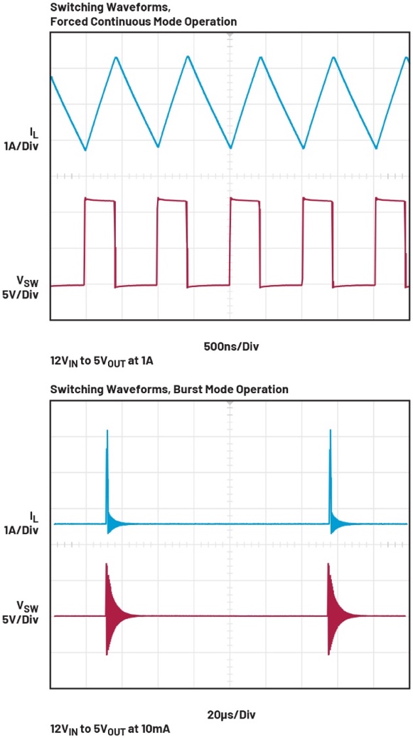
Figure 9: Switching waveforms for forced continuous mode and burst mode
As SoC performance continues to evolve, load current requirements are expected to increase further. As shown in Figure 10, two LT8648S/LT8648SP devices can be connected in parallel by linking their inputs and outputs, thereby increasing the load current they can handle. As shown in Figure 11, even when the load current exceeds 30 A, the output voltage deviation remains minimal. The devices automatically operate with phase-shifted switching during parallel operation, thereby preventing any deterioration in EMC performance.
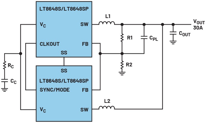
Figure 10: Two LT8648S devices connected in parallel
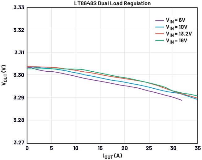
Figure 11: Load regulation of the LT8648S when two chips are operating in parallel
Conclusion
The LT8648S and LT8648SP are single-chip power management ICs with integrated FETs. Not only do they support high output currents, but they also deliver high-precision, highly stable output voltages across a wide input voltage range and a wide temperature range. Furthermore, they feature low EMC and low quiescent current—both of which are essential requirements for automotive electronics applications. Consequently, they are ideally suited for ECUs where compact size and high current-carrying capacity are required.

 English