Data Centre Power,Power Conversion,Everything is stored in the cloud these days, but where exactly is the cloud?
The answer is the data centre. Our endless demand for pictures, videos and other content is driving the data centre industry to boom.
According to the International Energy Agency (IEA), the rapid growth of the Artificial Intelligence (AI) industry is leading to a surge in data centre power demand. Data centre power consumption is expected to more than double in the three years between 2022 and 2025. This not only increases operating costs, but also puts a strain on aging power infrastructure, which is already overburdened and in need of massive investment and upgrades.
As power consumption in data centres increases dramatically, there is a more urgent need for power semiconductors that can convert power efficiently. This growing demand is driven by the need to reduce operating costs on the one hand, and to reduce greenhouse gas emissions on the other, in order to achieve net-zero emissions. In addition, the industry is constantly pursuing lower cost and smaller power systems.
Heat dissipation is another major challenge for data centres. It is estimated that most of today's data centre cooling systems consume more than 40% of the power. In fact, with power efficiency, wasted energy is mainly dissipated in the form of heat that needs to be emitted through the data centre's air conditioning system. Therefore, the more efficient the power conversion, the less heat is generated and, accordingly, the lower the power bill for heat dissipation.
AC-DC conversion requirements for data centres
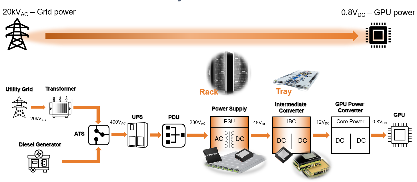
Let's take a closer look at the demands on data centre power systems and what device vendors are doing to address these challenges. Power densities within data centres are climbing at an accelerated rate, and power supply unit (PSU) vendors are committed to increasing the power capabilities of standard 1U racks (Figure 1). About a decade ago, the average power density per rack was about 4 to 5 kW, but today's hyperscale cloud computing companies, such as Amazon, Microsoft, or Facebook, typically require power densities in the range of 20 to 30 kW per rack, and some specialised systems require even more, with power densities of 100 kW or more per rack.
Grid power
GPU power
Utility Grid
Transformer
Diesel Generator
Rack
Tray
Power Supply
Intermediate Converter
GPU Power Converter
Core Power
Figure 1:Data centre power delivery - from grid to GPU
With limited space to store power supplies and space to dissipate and manage power conversion heat loss, high power densities require power supplies to be designed in compact, small form factors with high energy efficiency features.
However, the challenge is not only to improve overall energy efficiency, but power supplies must also meet the specific needs of the data centre industry. For example, all AI data centre PSUs should meet the stringent Open Rack V3 (ORV3) base specification.
Recently, server rack providers introduced a new AC-DC PSU with a nominal input range of 200 to 277 VAC and an output of 50 VDC that meets the ORV3 standard. The standard requires peak efficiencies of 97.5 per cent or more at 30 per cent to 100 per cent load and a minimum efficiency of 94 per cent at 10 per cent to 30 per cent load.
Topology Selection for Server Rack Power Supplies
Topology Selection for Server Rack Power SuppliesThe Power Factor Correction (PFC) stage is a key component of the AC-DC conversion in a PSU and is important for achieving high energy efficiency.The PFC stage is responsible for shaping the input current in order to maximise the ratio of useful power to total input power. The PFC design is also key to meeting Electromagnetic Compatibility (EMC) standards in regulations such as IEC 61000-3-2 and ensuring compliance with energy efficiency codes such as ENERGY STAR®.
For many applications, such as data centres, it is best to design the PFC stage using the ‘totem pole’ PFC topology. This topology is typically used for PFC function blocks in 3 kW to 8 kW system power supplies in data centres (Figure 2). The totem pole PFC stage is based on MOSFETs and improves the energy efficiency and power density of the AC power supply by removing the large and lossy bridge rectifiers.
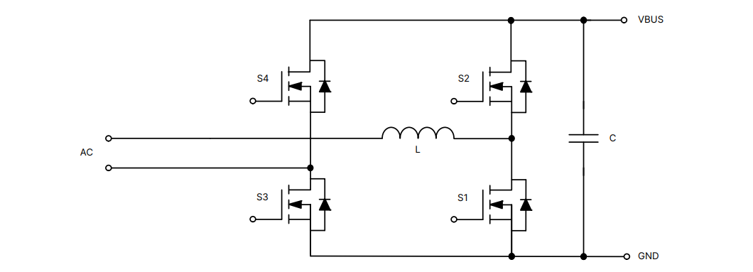
Figure 2:Totem pole PFC stage
However, in order to achieve the 97.5% or higher efficiency required by hyperscale data centre companies, totem pole PFCs need to use MOSFETs based on ‘wide bandwidth’ semiconductor materials such as Silicon Carbide (SiC.) Today, all PFC stages use SiC MOSFETs as the fast-switching bridge arm and Si-based superjunction MOSFETs as the phase or slow bridge arm. Today, all PFC stages use SiC MOSFETs as fast-switching bridge arms and silicon-based superjunction MOSFETs as phase or slow-speed bridge arms.
Compared to silicon MOSFETs, SiC MOSFETs offer better performance and efficiency, are robust and reliable, perform better at high temperatures, and can operate at higher switching frequencies.
Compared to silicon-based superjunction MOSFETs, SiC MOSFETs store less energy in the output capacitance (EOSS), which is critical to achieving low load targets, as switching losses in the PFC stage are primarily due to EOSS and relatively high gate charge. A lower EOSS significantly reduces energy loss during switching, thus improving the energy efficiency of the totem pole PFC fast bridge arm. In addition, SiC MOSFETs have a better positive temperature coefficient RDS(ON) than silicon-based superjunction MOSFETs due to the excellent thermal conductivity of SiC devices, which is three times that of silicon-based devices.
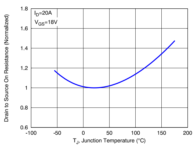
The following figure shows the on-resistance of a 650V SiC MOSFET versus junction temperature. (Fig. 3) (The on-resistance at a junction temperature of 175°C is 1.5 times higher than the on-resistance at room temperature.)
Drain to Source On Resistance (Normalized)
TJ, Junction Temperature (°C)
Figure 3:650V SiC MOSFET on-resistance versus junction temperature
Similarly, the figure below (Figure 4) shows the on-resistance of a 650 V superjunction MOSFET versus junction temperature. The on-resistance at a junction temperature of 175°C is more than 2.5 times higher than that at room temperature.
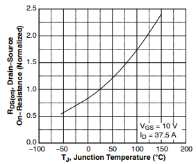
Figure 4:650 V Silicon Superjunction MOSFET On-Resistance vs. Junction Temperature
Comparing a silicon-based 650 V superjunction MOSFET with similar RDS(ON) ratings to a 650 V SiC MOSFET, the on-resistance (RDS(ON)) of the former improves to about 50 mohm at a junction temperature (Tj) of 175°C, whereas the RDS(ON) of the latter is about 30 mohm. During high-temperature operation, the 650 V SiC MOSFET has lower on-state losses. During high-temperature operation, the conduction loss of the 650 V SiC MOSFET is lower.
In the totem pole PFC slow bridge block and LLC block, conduction loss accounts for most of the total power loss, and the lower RDS(ON) of SiC MOSFETs at higher junction temperatures contributes to higher system efficiency.
SiC MOSFETs excel in the totem pole PFC topology due to their low RDS(ON) increase and high EOSS at high temperatures, which contributes to higher efficiency and lower energy losses.
New SiC MOSFET Technology Achieves Outstanding System Efficiency
ONSEMI's 650V M3S EliteSiC MOSFETs, including the NTBL032N065M3S and NTBL023N065M3S, provide superior switching performance and greatly improve system efficiency at the PFC and LLC levels. The M3S EliteSiC technology far exceeds the performance of its predecessor, with a 50 percent reduction in gate charge, a 44 percent reduction in EOSS and a 44 percent reduction in charge stored in the output capacitance (QOSS). When used in hard-switching topologies at the PFC level, the excellent EOSS performance further improves system efficiency at light loads. In addition, the lower QOSS simplifies the design of resonant storage inductors for LLC-level soft-switching topologies.
The M3S EliteSiC MOSFETs dissipate less heat due to their excellent switching performance and energy efficiency. In addition to helping to reduce heat dissipation requirements in data centres, the device can operate at lower temperatures in PFC and DC-DC blocks with high operating frequencies, such as in wall-mounted DC charging posts for electric vehicles (EVs).
In addition, the M3S EliteSiC MOSFETs offer superior gate charge Qg and reduced gate drive losses at the same voltage level. At the same time, the excellent Qgs and Qgd also help reduce switch turn-on and turn-off losses. In the LLC function block, the output capacitor needs to be charged when the VDS transitions from the off state to the diode on state. To do this quickly, a low transient output capacitance (COSS(TR)) must be used. Transient COSS is important here because it minimises cycling losses in the resonant storage and shortens the dead time of the LLC, thus reducing cycling losses on the primary side. Low on-resistance minimises conduction losses, while low EOFF helps to further reduce switching losses. Overall, improved system efficiency is a key performance criterion, making SiC MOSFETs the preferred solution for PFC and LLC stages in data centres.
The new EliteSiC MOSFETs are also well suited for energy infrastructure applications such as photovoltaic (PV) generators, energy storage systems (ESS), uninterruptible power supplies (UPS) and electric vehicle charging stations. Design engineers can use M3S EliteSiC MOSFETs to reduce overall system size, which in turn helps increase operating frequency. From a system perspective, M3S EliteSiC MOSFETs can help design engineers reduce system cost compared to silicon-based 650 V superjunction MOSFETs.
Overall, the new EliteSiC MOSFETs are comparable to superjunction MOSFETs on the market in terms of cost, EMI, high temperature operation and switching performance based on the same RDS(ON). The 650V M3S EliteSiC MOSFET in the same package achieves lower RDS(ON) than superjunction MOSFETs, contributing to improved system power efficiency in LLC topologies. The outstanding advantage over other silicon-based alternatives is the significant reduction in switching losses.

Figure 5:Benefits of 650V M3S EliteSiC MOSFETs
EMPOWER AI
650V M3S EliteSiC MOSFETS
Significant Performance Improvement
650V M3S EliteSiC MOSFET
EXCELLENT Eoss TO IMPROVE PFC EFFICIENCY
MEET OPEN RACK V3 BASE EFFICIENCY
EXCELLENT SWITCHING PERFORMANCE
INCREASE SYSTEM POWER DENSITY
LESS Qoss FOR EASY INDUCTANCE DESIGN
Reach a verdict
This paper briefly explores the higher standards for efficient power conversion imposed by the growing power demands of hyperscale data centres. Artificial Intelligence (AI) is expected to revolutionise the world, and there is an urgent need to improve energy efficiency in order for our existing power grids to meet the demands of the rapid growth of AI-driven cloud computing.
The use of SiC MOSFETs can significantly improve efficiency at both the PFC and LLC levels. ON Semiconductor's 650 V M3S EliteSiC MOSFETs can dramatically improve energy efficiency in the PFC and LLC stages of hyperscale data centres. 650 V M3S EliteSiC MOSFETs have lower gate charge, EOSS and QOSS, which can help reduce power consumption by improving efficiency and simplifying the design of hard-switching topologies in the PFC and LLC stages. consumption and lower operating costs.

 English










