In the signal processing process, the time-domain truncation will lead to the phenomenon of spectral leakage. What is the fundamental cause of it? What methods can be used to mitigate this effect? This paper takes the ADC performance test scenario as an example to explore the effects and issues associated with non-periodic truncation of ADC output results.
Two Points
1. Two Key Issues
For better signal analysis or processing, it is necessary to observe the original signal from the frequency domain rather than the time domain in practical applications. However, from a physical standpoint, only the time-domain info of the signal can be directly obtained. To obtain the frequency-domain info of the signal, Fourier Transform is required to calculate the spectrum of the original signal. But, for a computer, there are two key issues when doing this calculation:
• The computer can only handle digital signals, not the analog signals from real life.
• The signals to be analyzed are theoretically of infinite duration.
2. Addressing the Issues
Regarding the first issue, the computer needs to first sample and quantize the incoming analog signal into a digital signal, then use Discrete Fourier Transform (DFT) to calculate the spectrum of the original signal. In addition, it is necessary to know that the Fast Fourier Transform (FFT) is essentially a fast algorithm based on DFT.
According to the second issue, due to the computational load or real-time processing requirements, the actual signal data collected is usually truncated into blocks of data (frames), which are then subjected to DFT analysis. If the truncated signal was originally periodic, depending on the truncation method, it can be categorized into two types: periodic truncation (also called coherent sampling) and non-periodic truncation (also called incoherent sampling).
3. Time Domain Perspective
Let’s first understand from the time-domain perspective how periodic and non-periodic truncation affect the DFT. Intuitively, DFT is a discrete-time Fourier transform (DTFT) applied to the truncated signal, and the result is sampled in the frequency domain with a periodic main value. If you perform DFT analysis on a sine wave with periodic truncation, it corresponds to a periodic shift and concatenation of the truncated signal in the time domain, resulting in the same signal as the original.
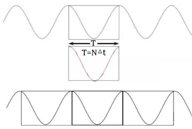
Figure 1: Periodic Truncation
However, if non-periodic truncation is performed, the concatenated signal is no longer the same as the original signal. This means the newly generated signal contains new components at different frequencies from the original signal, leading to the phenomenon of spectral leakage.
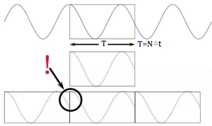
Figure 2: Non-periodic Truncation
4. Frequency Domain Perspective
Now, let’s examine this process from the frequency domain perspective. Time-domain truncation of the original signal is equivalent to convolving the original signal's spectrum with the spectrum of the truncation window function. This convolution inevitably causes the deformation of the original signal's spectrum.
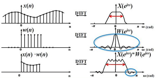
Figure 3: Spectral Leakage Caused by the Convolution of the Signal Spectrum with the Window Function Spectrum During the Truncation.
To analyze ADC performance, a common approach is to input a sine wave with a known frequency to the ADC, then sample and perform FFT analysis on the output. The original frequency spectrum of a single-frequency sine wave is shown in Figure 4:
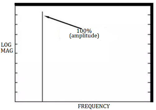
Figure 4: Half-spectrum of the Sine Wave
If the truncation process is non-periodic, the resulting FFT spectrum will show that the original signal's spectrum begins to tail off and widen. This naturally affects the subsequent analysis of the ADC's performance.
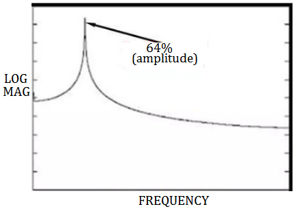
Figure 5: Spectrum after Leakage
Non-periodic truncation is equivalent to choosing sampling parameters for the ADC such that the total time duration of the truncated signal satisfies:
N*Ts = K * Tin
where,
K is not an integer,
Ts is the sampling interval,
Tin is the input signal period,
N is the number of sampling points.
Assuming an N-point DFT is performed (usually with DFT point count equal to the number of sampling points, which is the minimum required to avoid time-domain aliasing), the frequency interval in the DFT spectrum is Fs/N (where Fin = K * Fs/N, is the input signal frequency, and Fs is the sampling frequency). This means the input signal does not fall exactly on an integer multiple of the frequency resolution Fs/N. Consequently, in the DFT spectrum after sampling, no frequency component matches the original signal frequency exactly. In reality, the fundamental cause of spectral leakage lies in the time-domain multiplication, which is equivalent to frequency-domain convolution, causing the deformation of the original signal’s spectrum. Therefore, the peak frequencies in the DFT spectrum are only close to, but not exactly equal to the original signal's frequencies.
DTFT vs. DFT
Theoretical Analysis
Let’s further compare the Discrete-Time Fourier Transform (DTFT) and DFT. If the original signal before sampling is a single-frequency periodic signal cos(w0*n), the frequency spectrum after time-domain sampling is a series of periodic impulse sequences (right-side diagram 1), corresponding to a periodic frequency domain. After truncation by a rectangular window, the time-domain multiplication of the original signal and the window function corresponds to a convolution of their spectra in the frequency domain (right-side diagram 2). As a result, the original single-frequency input spectrum undergoes spectral leakage and transforms into a superposition of periodic functions (right-side diagram 3), which is the continuous spectrum in the DTFT result. Thus, if you only look at the DTFT spectrum, spectral leakage is inevitable after time-domain truncation.
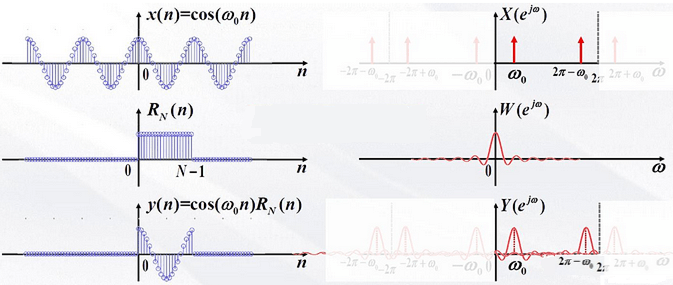
Figure 6: Time-domain Truncation Leading to Frequency-domain Convolution.
The DFT result can be viewed as the frequency-domain sampling of the DTFT result, followed by taking the periodic main value (frequency-domain sampling corresponds to time-domain periodicity). However, after frequency-domain sampling, if the sampling points fall on zero-crossings of the Sinc function in regions other than where the signal's frequency components reside, the spectral leakage caused by the Sinc function's oscillations will not be observed in the DFT result.
In summary, the DTFT spectrum is continuous (with a period in digital angular frequency 2n), while the DFT spectrum is discrete, with the frequency line spacing given by 2n/N, where N is the number of sampling points, which is also the length of the truncation window. Due to limitations in computational power and storage depth, computers can only process discrete digital signals, not continuous signals (continuous signals can be approximated as having an infinite number of discrete samples). Therefore, in practical applications, the result we observe is the DFT, not the DTFT. FFT is essentially a fast algorithm based on DFT to speed up the computation.
Mathematical Analysis
Formula Analysis
The DTFT of cos(w0*n) is 
In the above formula, k is an integer. The DTFT of the rectangular window function RN(n)=[u(n)–u(n-N)] is 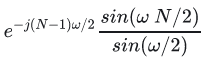
Since we cannot process infinitely long signals, we need to truncate the signal, that is, multiply the original signal with the rectangular window function cos(w0*n)*RN(n). The DTFT of the truncated signal is:

For simplicity, we can only observe the convolution of one of the unit sampling sequences with the rectangular window function (k = 0), and the result is 
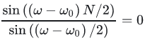
When 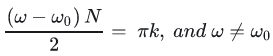 , there is
so we can get 
k is an integer, N is the length of the rectangular window function, and the default is also the total number of sampling points in the frequency domain when performing DFT later. Assuming that the truncation satisfies the periodic truncation and the N-point DFT is performed on the truncated result, the spectrum interval is 2п/N (from the perspective of digital angular frequency), and the periodic truncation ensures 
Where,
f0 is the original signal frequency,
fs is the sampling frequency,
w0 is the corresponding digital angular frequency after sampling.
So after DFT analysis, the discrete digital angular frequencies of its independent variables all satisfy

In this case, A is an integer representing the (A+1)-th sampling point in the DTFT. From the DFT frequency domain components, it can be seen that they coincide with the zero-crossings in the DTFT. Therefore, except at w = wo, the magnitude of the DFT is zero at all other frequencies. This means that the frequency spectrum of the truncated signal in the DTFT is distorted, but the DFT is essentially sampling the DTFT spectrum. Aside from sampling the peak values of the original signal spectrum, the remaining sampled points align exactly with the zero-crossings of the convolved spectrum of the original signal and the window function, which helps avoid observing spectral leakage in the DFT result. This difference can be intuitively seen in the curve shown in the figure below. Whether or not periodic truncation is performed, the DTFT results are shown by the dashed line. However, when observing the DFT results—marked by circles in the figure (with the top showing periodic truncation and the bottom showing non-periodic truncation)—it can be seen that periodic truncation eliminates the spectral leakage phenomenon that occurs in the DTFT.
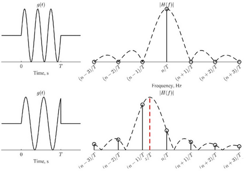
Figure 7: The Impact of Periodic and Non-periodic Truncation on the DFT in DTFT Sampling Results.
Returning to the FFT analysis of the ADC output bitstream in Cadence, we continue with the non-periodic truncation results. However, when switching the rectangular window to a Blackman window, the new FFT result still exhibits some deviations. To completely avoid spectral leakage in DFT analysis, recall that windowing in the frequency domain corresponds to the convolution of the original signal’s spectrum with the window function. In order to avoid distortion of the signal spectrum after convolution, the frequency spectrum of the window function should be a unit impulse sequence, which also means that the window is an infinite-length rectangular window in the time domain. This clearly conflicts with the goal of achieving signal truncation.
Unlike ADC performance testing, where the focus might be on whether spectral leakage occurs at a single frequency point in the input signal spectrum, in actual spectral analysis, the relative energy between different frequency components is of greater concern. This means that the input signal may contain multiple frequency components at different frequencies, and since the exact frequencies of interest are not known in advance, it is not possible to avoid spectral leakage through periodic truncation. In such cases, besides using windowing to suppress spectral leakage, one can also increase the number of sampling points when performing FFT analysis. That is, the length N of the time-domain sequence x(n) should be made larger. In this way, even if the FFT spectrum does not show a corresponding frequency point of the signal, the frequency resolution of the spectrum fs/N becomes smaller, which can help reduce the impact of spectral leakage to some extent.
A Brief Note
1. Sampling for Frequency Analysis: When using DFT to analyze the spectrum of a signal, the signal must first be sampled. Time-domain sampling leads to periodic extension in the frequency domain. To avoid spectral aliasing, the sampling frequency must be at least twice the highest frequency in the signal (Nyquist sampling theorem). This is why an anti-aliasing filter is applied before ADC input.
2. Windowing and Spectral Leakage: Due to the impossibility of processing infinite-length signals, the digitized signal must be truncated using a window function. In the frequency domain, this corresponds to convolving the signal spectrum with the window function's spectrum, causing spectral leakage. This effect cannot be completely avoided using windowing or increasing sampling points, but it can be mitigated.
3. The spectrum seen by DTFT is a continuous spectrum. In order for the computer to analyze and process it, it is also necessary to sample the frequency-domain spectrum of DTFT, that is, to perform DFT operation to obtain a discrete frequency domain spectrum. The frequency interval of the spectrum components in DFT is sampling frequency/number of sampling points, and the frequency domain sampling operation is extended for the time domain period.
So reasonable actions are necessary. On the one hand, in order to avoid time domain aliasing, the number of frequency domain sampling points should be equal to or greater than the total sequence length of the original input digital signal (the default number of DFT points is equal to the number of time domain sampling points). If the sequence length of the input digital signal is too short, it will cause a fence effect (intuitively speaking, since the number of DFT points is equal to the sequence length, the frequency interval in the DFT result is too large if the number of DFT points is too small, and the DTFT result cannot be well fitted). The solution is to add zeros after the original digital signal sequence, thereby increasing the number of frequency domain sampling points to better fit the DTFT result. On the other hand, if the input signal is a single-frequency periodic signal, the spectrum leakage phenomenon that occurs in DTFT can be avoided in DFT sampling by setting parameters reasonably for periodic truncation.
Conclusion
In reality, the signal is finite and often not perfectly periodic within the analysis window. As a result, the energy of the signal leaks into adjacent frequency bins, causing a distortion in the frequency spectrum. In short, understanding spectral leakage and applying appropriate techniques, such as windowing, increasing the sampling length, and using DFT, can help reduce the impact of spectral leakage when analyzing signals in practical applications.

 English










