Zener diode is a semiconductor component with high resistance up to a critical reverse breakdown voltage. It outputs a stable low ripple voltage under the condition of load current variation, the DC output voltage of the half-wave or full-wave rectifier is superimposed on the ripple of the DC voltage, and as the load value changes, the average voltage output will also change. In this way, a more stable voltage is generated.
Zener Diode Basic
Terminology
Zener diode is a surface-contact crystal diode made of silicon semiconductor material. Using the reverse breakdown state of the PN junction, the current can change in a wide range while the voltage is basically unchanged.
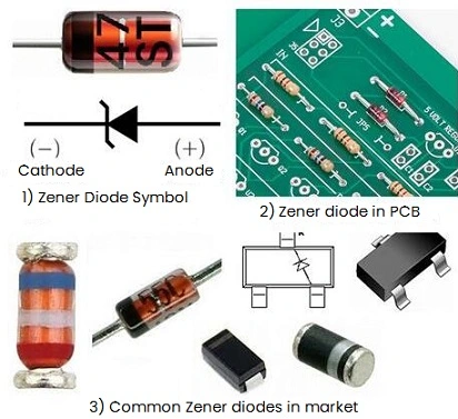
* Positive (+) and Negative (-) Distinction
1) From the appearance, the positive electrode of the metal-packed Zener diode body is flat, and the negative electrode is semicircular.
2) The end of the plastic Zener diode with the color code printed on it is the negative pole, and the other end is the positive pole.
3) For Zener diodes with unclear signs, you can also use a multimeter to determine their polarity, and the measurement method is the same as that of ordinary diodes.
Working Principle
The characteristic of the Zener diode is that after breakdown, the voltage at both ends remains unchanged. It is generally connected in parallel in the circuit to shunt and stabilize the voltage, and can work normally in the breakdown state. However, several Zener diodes cannot be connected in parallel at the same time, because their parameters are discrete, and it is difficult to find exactly the same ones. In addition, if the voltages are different, the voltage regulation value is determined by the lower one. After the Zener tube is connected to the circuit, if the voltage of each point in the circuit changes due to fluctuations in the power supply voltage or other reasons, the voltage at both ends of the load will remain unchanged.
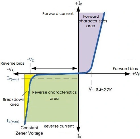
Figure 1: V-I Characteristics of Zener Diode
State ①: Forward bias state
In this state, the characteristics of the Zener diode show the characteristics of ordinary diodes, that is, as the forward bias voltage increases, the forward current changes greatly and the curve is very steep. Since Vf (about 0.3V~0.7V) is very small, this forward bias state is basically useless. It should be noted that the forward voltage drop of different Zener diodes is different.
State ②: Reverse bias state
When the reverse voltage does not reach Vz, the Zener diode is basically not turned on; and when the reverse bias voltage is close to Vz, it starts to conduct, generating Ir current. In addition, as the reverse bias voltage increases, the reverse current Ir will also vary greatly. Although the current changes in a large range, the voltage across the diode is basically stable near the breakdown voltage, thereby realizing the voltage stabilizing function. The yellow area (breakdown area) in the figure is the normal working state of the Zener diode. Usually, the range of Vr corresponding to this area is very small, and this voltage is the working point and voltage regulation value of the Zener diode.
Figure: Volt-ampere Characteristics of a Zener Diode
Main Parameters
Refers to the stable voltage value generated at both ends of the tube when it passes the rated current. This value varies slightly with operating current and temperature. Due to the difference in manufacturing process, the voltage regulation value of the same type of voltage regulator tube is not exactly the same.
Stable current (Iz):
The reverse current when the operating voltage is equal to the steady voltage. When the components are working, the reverse basic current that passes through is small, so the voltage stabilization effect will become poor; but too large current will cause the tube to be damaged due to excessive temperature. When diode’s current is lower than Iz, the voltage stabilization effect will become worse; on the contrary, when higher than this value, as long as the rated power loss is not exceeded, the voltage stabilization performance will also be better, but it consumes more power.
Dynamic resistance (Rz):
When the Zener diode is working, we hope that the stable voltage change should be as small as possible when the current variation range is large. In order to accurately reflect this performance, it is stipulated that the ratio of the voltage change to the current change is called the dynamic resistance of the Zener diode, which changes with different operating currents. Generally, the larger the operating current, the smaller the dynamic resistance, the better the performance of the Zener diode.
Dissipated power (Pz):
When the reverse current passes through the PN junction, a certain power loss will be generated, and the temperature of the PN junction will also increase. The power dissipation of the tube is determined according to the allowable operating temperature of the PN junction, and small power tubes are usually about a few hundred milliwatts to several watts.
Maximum dissipated power (Pzm):
Refers to the maximum power loss of the Zener tube depends on the area of the PN junction and conditions such as heat dissipation. When working in reverse, the power loss of the PN junction is: Pz=Vz*Iz, and Izmax can be determined by Pzm and Vz.
Temperature coefficient (Ctv):
In the Zener tube, when |Vz|>7V, Vz has a positive temperature coefficient, and the reverse breakdown is an avalanche breakdown. When |Vz|<4V, VZ has a negative temperature coefficient, and the reverse breakdown is Zener breakdown. When 4V<|Vz|<7V, the Zener tube can obtain a temperature coefficient close to zero. Such Zener diodes can be used as standard Zener tubes. For example, the Ctv of 2CW58 voltage regulator tube is +0.07%/°C, that is, every time the temperature rises by 1°C, its voltage regulator value will increase by 0.07%. In the case of relatively high power requirements, two Zener tubes with opposite temperature coefficients can be connected in series as compensation.
Reverse Leakage Current (IR):
Refers to the leakage current generated by the Zener diode under the specified reverse voltage. For example, when VR=1V of 2CW58 regulator tube, IR=0.1uA; when VR=6V, IR=10uA.
Compare with Ordinary Diodes
Diodes generally work under forward voltage, while Zener tubes work under reverse breakdown state.
The reverse breakdown voltage of ordinary diodes is generally above 40V, and the high one can reach hundreds of volts to thousands of volts, and the volt-ampere characteristic curve is not steep in reverse breakdown area, that is, the range of reverse breakdown voltage is large. The dynamic resistance is also relatively large. For Zener tubes, when the reverse voltage exceeds its operating voltage Vz (also known as Zener voltage or stable voltage), the reverse current will suddenly increase, while the voltage across the device remains basically constant. The corresponding reverse V-I characteristic curve is very steep, and the dynamic resistance is very small. According to this, Zener tubes can be used as voltage regulators, voltage references, overvoltage protection, level shifters, etc.
Application Circuits of Zener Diodes
Zener Diode Circuits and Calculation
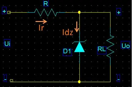
Figure 2: Simple Voltage Regulator Circuit
This circuit utilizes the voltage stabilizing characteristics of the Zener diode to achieve voltage stabilization, but the output current is very small.
Grid voltage fluctuations:

Load change:

This following circuit utilizes the voltage stabilizing characteristics of the Zener diode to achieve voltage stabilization and can output a larger current.
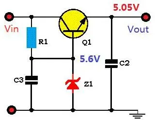
Figure 3: Improved Voltage Regulator Circuit
This following circuit uses the reverse bias characteristic of the Zener diode to prevent the LED from being damaged by excessive static electricity.
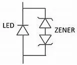
Figure 4: ESD Protection Circuit For LED Lights
If the output voltage is too high, the Zener diode in this circuit will conduct, and then trigger the SCR to limit the input voltage terminal.
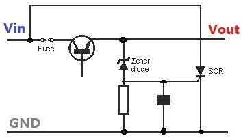
Figure 5: Overvoltage Protection Circuit
If the input signal is too large, it is easy to damage the op amp OP, and the amplitude of the Input signal can be limited by placing a Zener diode. Note that in this case, D1 with a small reverse leakage current should be selected; if the signal frequency is too high, the equivalent capacitance of D1 should also be considered to be small enough.
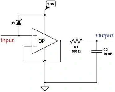
Figure 6: Signal Clipping Circuit
Selection
1) When the conduction voltage is low, choose a germanium tube.
2) Silicon tubes are selected for hours of reverse current.
3) When the conduction current is large, select the surface combination type.
4) Select point contact type when the working frequency is high.
5) Silicon tubes are selected when the reverse breakdown voltage is high.
6) Silicon tubes are selected for high temperature resistance.
The voltage stabilization value of the Zener diode is very discrete, even if the same model of products from the same manufacturer, it is not exactly the same. Therefore for circuits with higher requirements, the voltage stabilization value should be tested before selection.
For Zener diodes used for overvoltage protection, the selection of its stable voltage should be based on the size of the protection voltage, not too large or too small, otherwise it will not play the role of voltage protection.
When select, in addition to paying attention to parameters such as stable voltage and maximum operating current, a smaller dynamic resistance should keep an eye on, because the smaller the dynamic resistance, the better the voltage stabilization performance.
When using a Zener tube, it should be noted that the reverse current of the diode cannot increase infinitely, otherwise it will cause overheating and damage to the diode. Therefore, the Zener tubes generally require a series current limiting resistor in the circuit.
During selection, it should be considered according to the specific electronic circuit. For a simple parallel stabilized power supply, the output voltage is the stable voltage of the tube.
Zener Diode Components
Common Zener Diodes
a) 78xx series: 7805, 7812, 7824, etc. They are mainly used for positive voltage regulation and can output fixed positive voltage values, such as 5V, 12V, 24V, etc.
b) LM317: A three-terminal voltage regulator with adjustable output voltage, which is widely used in power supply design to achieve accurate voltage output.
c) LM7805: Positive Zener diode, the output voltage is fixed at 5V.
d) LM2940: 1A low dropout positive voltage regulator diode, which can output higher current and work more stably at low voltage.
e) LT1083: A high-voltage, high-current regulator capable of outputting voltages from 2.5V to 28V with a maximum current of 7.5A.
f) ZXLD1350: A voltage regulator commonly used in LED drive circuits, its output current can reach 1A, and it can provide stable current output.
Model Lists in Market
|
|
Model
|
Voltage
|
Model
|
Voltage
|
Model
|
Voltage
|
|
500mW
|
1N4614
|
1.8V
|
1N4622
|
3.6V
|
1N4099
|
6.8V
|
|
1N4615
|
2V
|
1N4622
|
3.9V
|
1N4100
|
7.5V
|
|
1N4616
|
2.2V
|
1N4623
|
4.3V
|
1N4101
|
8.2V
|
|
1N4617
|
2.4V
|
1N4624
|
4.7V
|
1N4102
|
8.7V
|
|
1N4618
|
2.7V
|
1N4625
|
5.1V
|
1N4103
|
9.1V
|
|
1N4619
|
3V
|
1N4626
|
5.6V
|
1N4104
|
10V
|
|
1N4620
|
3.3V
|
1N4627
|
6.2V
|
1N4105
|
11V
|
|
1N4106
|
12V
|
1N4113
|
19V
|
1N4120
|
30V
|
|
1N4107
|
13V
|
1N4114
|
20V
|
1N4121
|
33V
|
|
1N4108
|
14V
|
1N4115
|
22V
|
1N4122
|
36V
|
|
1N4109
|
15V
|
1N4116
|
24V
|
1N4123
|
39V
|
|
1N4110
|
16V
|
1N4117
|
25V
|
1N4124
|
43V
|
|
1N4111
|
17V
|
1N4118
|
27V
|
1N4125
|
47V
|
|
1N4112
|
18V
|
1N4119
|
28V
|
1N4126
|
51V
|
|
1N4127
|
56V
|
1N4130
|
68V
|
1N4133
|
87V
|
|
1N4128
|
60V
|
1N4131
|
75V
|
1N4134
|
91V
|
|
1N4129
|
62V
|
1N4132
|
82V
|
1N4135
|
100V
|
|
|
Model
|
Voltage
|
Model
|
Voltage
|
Model
|
Voltage
|
|
1W
|
1N4727
|
3V0
|
1N4740
|
10V
|
1N4753
|
36V
|
|
1N4728
|
3V3
|
1N4741
|
11V
|
1N4754
|
39V
|
|
1N4729
|
3V6
|
1N4742
|
12V
|
1N4755
|
43V
|
|
1N4730
|
3V9
|
1N4743
|
13V
|
1N4756
|
47V
|
|
1N4731
|
4V3
|
1N4744
|
15V
|
1N4757
|
51V
|
|
1N4732
|
4V7
|
1N4745
|
16V
|
1N4758
|
56V
|
|
1N4733
|
5V1
|
1N4746
|
18V
|
1N4759
|
62V
|
|
1N4734
|
5V6
|
1N4747
|
20V
|
1N4760
|
68V
|
|
1N4735
|
6V2
|
1N4748
|
22V
|
1N4761
|
75V
|
|
1N4736
|
6V8
|
1N4749
|
24V
|
1N4762
|
82V
|
|
1N4737
|
7V5
|
1N4750
|
27V
|
1N4763
|
91V
|
|
1N4738
|
8V2
|
1N4751
|
30V
|
1N4764
|
100V
|
|
1N4739
|
9V1
|
1N4752
|
33V
|
|
|
HITACHI
|
Model
|
Voltage
|
Model
|
Voltage
|
Model
|
Voltage
|
|
0.5W
|
HZ3A1
|
2.5V~2.7V
|
HZ3A2
|
2.6V~2.8V
|
HZ3A3
|
2.6V~2.9V
|
|
HZ3B1
|
2.8V~3.0V
|
HZ3B2
|
2.9V~3.1V
|
HZ3B3
|
3.0V~3.2V
|

 English










