Electrical grounding refers to connecting a circuit to the earth to form the circuit's reference point and current loop. That is, in the power system, a conductor is used to make a good electrical connection between the neutral point, shell or bracket of the electrical devices and the grounding device. Grounding is one of the important methods to suppress electromagnetic interference and improve the EMC performance of electronic equipment. Further more, correct grounding can not only improve the product's ability to suppress electromagnetic interference, but also reduce the product's external EMI emissions.
Electrical Grounding Basic
Grounding Methods
Grounding can prevent equipment and lines from being damaged, prevent fires, lightning strikes, electrostatic damage, and ensure the normal operation of the power system. It can also prevent people from suffering electric shocks that may cause life-threatening consequences. So what are the connection methods for this line protection measure? Here are some commonly used grounding methods.
1. Single-point Grounding
(1) Characteristics: Only one physical point in the circuit is defined as the ground reference point, and everything that needs to be grounded is connected here.
(2) Disadvantages: Not suitable for high-frequency applications.
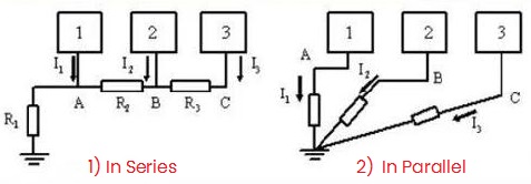
Figure 1: Single-point Grounding
Notes:
1) Do not use it in a system where high-power and low-power circuits are mixed. Because the ground current in high-power circuits will affect the normal operation of low-power circuits.
2) The most sensitive circuit should be placed at point A, where the potential is the most stable.
3) The solution to the shortcomings of single-point grounding is using parallel connection. However, parallel single-point grounding requires more wires. In practice, series and parallel mixed grounding can be used.
2. Series Single-point & Parallel Single-point Mixed
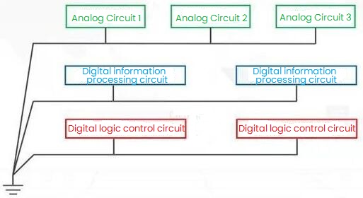
Figure 2: Series Single Point & Parallel Single Point Mixed
Notes:
(1) Group circuits according to their characteristics. Circuits that are not likely to interfere with each other are placed in the same group, and circuits that are prone to interference with each other are placed in different groups.
(2) Series single-point grounding is used in each group to obtain the simplest ground structure; then parallel single-point grounding is used for different groups to avoid mutual interference.
The key to this method: Never allow circuits with widely different power levels or circuits with different noise levels to share a ground wire. And these different grounds can only be connected at one point.
3. Multi-point Grounding
(1) Method: All points that need to be grounded are directly connected to the grounding plane closest to it, so that the length of the grounding wire is the shortest.
(2) Disadvantages: Maintenance is troublesome.
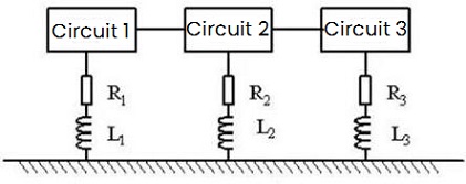
Figure 3: Multi-point Grounding
Notes:
(1) In order to reduce the ground inductance, multi-point grounding is often used in high-frequency and digital circuits. For example, in a multi-point grounding system, each circuit is connected to the nearest low-impedance ground plane, such as a chassis. And the ground wire of the circuit should be kept as short as possible to reduce inductance. In systems with very high frequencies, the ground wire is usually controlled within a few millimeters.
(2) Common impedance coupling problems are likely to occur when grounding at multiple points. In low-frequency situations, this problem can be solved through single-point grounding. But at high frequencies, it is necessary to reduce the ground impedance (common impedance). Due to the skin effect, current only flows on the surface of the conductor, so increasing the thickness of the conductor does not reduce the resistance. However, placing silver on the surface of a conductor can reduce the resistance of the conductor.
(3) Generally, below 1MHz, single-point grounding can be used; above 10MHz, multi-point grounding can be used; at 1MHz~10MHz, if the longest grounding wire does not exceed 1/20 of the wavelength, single-point grounding can be used, otherwise multiple-point way is better.
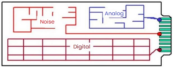
Figure 4: Grounding Wires on PCB
4. Mixed Grounding
The large-area copper grounding in the PCB is actually multi-point grounding, so does a single-sided PCB. Most multi-layer PCBs are high-speed circuits, the addition of ground layers can effectively improve the electromagnetic compatibility of PCBs, which is a basic way to improve signal anti-interference.
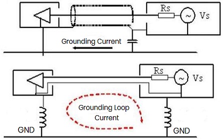
Figure 5: Mixed Grounding
Notes:
(1) The capacity of the grounding capacitor is generally below 10nF, depending on the frequency at which grounding is required.
(2) If the safety ground of the equipment is disconnected, the ground loop will be cut off, which can break the interference. However, for safety reasons, the chassis must be connected to a safe ground, and the grounding system shown in the picture above solves this problem. For higher-frequency ground loop currents, the ground wire is disconnected; while for 50Hz AC, the chassis is reliably grounded.
Grounding Classification
According to the different grounding functions, they can be divided into two categories:
1. Functional
1) System grounding is also called working grounding. Its purpose is to make the potential between the neutral point of the power grid and the earth close to zero. In order to keep the system running properly, it is very detrimental to the insulation of lines and equipment, and the increase in voltage also increases the risk of electric shock.
2) Logical grounding ensures that weak current systems have a stable zero-potential reference point for normal operation. Otherwise, the weak current system may not work properly.
3) Signal grounding is set to ensure that the signal has a stable reference potential.
2. Protective
1) Protective grounding is to reduce the contact voltage of the electrical device shell when a ground fault occurs and prevent personal contact with the metal shell and receive an electric shock.
2) Lightning protection grounding is to protect buildings and their electrical equipment from damage by lightning strikes and introduce lightning current into the earth.
3) Anti-static grounding is used to reduce the accumulation of static electricity that cause harm to equipment, especially in places with flammable goods, explosive pipelines and other places. It is set up to avoid sparks, fires or explosions caused by potential differences between pipelines.
Grounding Materials
1. Copper Conductor
It is a commonly used grounding conductor with good electrical conductivity, corrosion resistance and other advantages. Its disadvantages are poor thermal stability and heavy metal pollution. In some areas, copper-plated steel rods can be used as vertical grounding bodies or conductors for grounding grids.
2. Galvanized Flat Iron
Galvanized steel is used as grounding material due to its good thermal stability.
3. Electroplated Copper
The electroplated copper ground electrode uses special technology to evenly cover 99.9% pure copper on the low carbon steel core, so that the copper molecules and steel molecules are completely combined. It has the characteristics of thick copper layer, good viscosity and non-peeling, strong pressure resistance, corrosion resistance, stable low resistance and good plasticity. In short, it has the characteristics of both copper and steel.
4. Nano Carbon Flat Steel
Nano anti-corrosion conductive material is a further product based on the research on graphite and nickel powder materials. It has excellent electrical conductivity, corrosion resistance, impact resistance and thermal stability. When subjected to large current impacts caused by lightning or short circuit accidents, the conductive coating will not be easily burned and has high reliability.
|
Material
Parameter
|
Thermal Stability
|
Electrical Conductivity
|
Corrosion Resistance
|
Price
|
|
Copper
|
Poor
|
Good
|
Good
|
High
|
|
Galvanized steel
|
Good
|
Poor
|
Poor
|
Cheap
|
|
Copper plated steel
|
Poor
|
Good
|
Good
|
Moderate
|
|
Nano carbon flat steel
|
Good
|
Good
|
50 years
|
Moderate
|
Based on the above comparison, it is easy to see that copper-plated rods and nano carbon flat steel are good grounding materials.
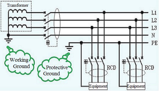
Figure 6: Grounding System (TT)
Electrical Grounding Problems
1. Cause Analysis
1) Poor grounding of wires: If the ground wire is not firmly connected or the ground resistance is too large, the ground resistance of the power system will increase, failing to meet the design requirements and easily causing ground faults.
2) Equipment insulation damage: During operation, the equipment of the power system suffers from overvoltage shocks and electric energy pulses, and long-term operation leads to equipment insulation aging and damage, etc., resulting in leakage current and easily inducing ground faults.
3) Structural defects of the power system: The power system grounding mode is improperly selected, effective grounding protection measures are not adopted, and the power system is grounded at a single point, resulting in structural defects such as an increase in the ground potential of the load capacitor loop, which can easily cause ground faults.
4) External factors: When public distribution lines of the power system cross roads and water canals, failure to take protective measures as required during building foundation construction, insufficient laying depth and other factors may easily cause grounding faults.
5) Misoperation of the system: During the operation and maintenance of the system, if the operation is improper or the settings are incorrect, abnormal operations such as the opening of the ground gap and unexpected power outage of the line will occur, resulting in the occurrence of ground faults.
In summary, power system ground faults are caused by a variety of reasons. During the operation and maintenance process, it is necessary to take the management and maintenance of equipment regularly, and strictly enforce operating procedures to ensure the safe operation of power system equipment and reduce the occurrence of ground faults.
2. Solutions
1) Carry out regular maintenance inspections on the power system to detect and deal with faults in a timely manner.
2) Check the insulation status of the equipment to reduce problems in a timely manner.
3) Take a comprehensive analysis of past failures and formulate corresponding solutions to prevent similar failures from occurring.
4) Introduce precision monitoring technology to monitor various data of the power system in real time and accurately to facilitate timely detection of faults. That is, the power system should be grounded as needed and should be inspected and maintained regularly in compliance with relevant regulations and standards.

 English










