The function of a general oscillation circuit is to generate oscillations, which have different frequencies and can make the circuit work within a stable frequency range. The role of the crystal oscillator is to pace the benchmark, stabilize the frequency, and select the frequency. And it can be used in almost all industries, technology, automotive, digital, electronics and other fields. Among this, the capacitor plays an important role in the crystal oscillator circuit.
Capacitors in Oscillation Circuit
Oscillation Circuit
Oscillation circuit is commonly used to generate a repeating waveform for electronics applications. In terms of this circuit, oscillator can be used to generate any type of waveform, including sine waves, square waves, and triangle waves.
The oscillator mainly has an LC circuit composed of a capacitor and an inductor and freely oscillates through the mutual conversion of electric field energy and magnetic field energy. To maintain the oscillation, an amplifier circuit with positive feedback is needed. And meanwhile, LC oscillators are divided into transformer-coupled and three-point oscillators, many quartz crystal oscillators using quartz crystals, and LC oscillators with integrated operational amplifiers.
The function of the oscillation circuit is to provide the basic clock signal for the system. Its general structure is to connect a crystal oscillator to both ends of an inverting amplifier, then two capacitors are connected behind the crystal oscillator, and the other end of each capacitor is connected to ground. The capacity values of these two capacitors in series should be equal to the load capacitance. Please note that the pins of general ICs have equivalent input capacitance, which cannot be ignored. In addition, the load capacitance of a general crystal oscillator is 12.5pF or 15pF. If the equivalent input capacitance of the component pin is also considered, it is better to use two 22pF capacitors to form the oscillation circuit with crystal oscillator.
External Capacitors in Oscillation Circuit
1. As Basic Part
The crystal oscillator generates electrical signals through the structure and vibration frequency to ensure that the circuit works steadily and orderly. Further more, crystal oscillators are divided into active crystal oscillators and passive crystal oscillators. The passive crystal oscillator needs the help of a clock circuit to produce oscillation, and the solution is, it needs a matching capacitor to work; the active crystal oscillator is a complete resonant oscillator. So the capacitor can provide the necessary stable working conditions for the passive crystal oscillator circuits. As shown in the following:
1) Affects the oscillation frequency of the crystal oscillator.
2) Ensure the stability of the oscillation circuits.
Another important role of the capacitor is to ensure the stability of the crystal oscillator, which determines the performance of the circuit. The crystal oscillator capacitor can provide necessary stability factors, such as capacitance change rate, capacitance temperature coefficient, capacitance quality factor, etc., to ensure that the circuit can oscillate normally and stably to generate signals under different working conditions.
3) Improve crystal oscillator accuracy
Capacitors can also improve the accuracy of the crystal oscillator to ensure signal quality and system stability. In crystal oscillator circuit, capacitors improve the stability and accuracy of the circuit by optimizing factors such as capacitance value and capacitor quality. At the same time, it can also make the entire circuit have better linearity and spurious suppression capabilities in terms of frequency response, and is widely used in fields such as high-frequency signal transmission, measurement and control.
2. Load Capacitance
The crystal oscillator circuit is the heart of the microcontroller, and its accuracy is very important, so it is necessary to select components with a high Q value.
1) Matching capacitance
There is not only one crystal oscillator in a passive oscillation circuit. In order to meet the resonance conditions and allow the crystal oscillator to work normally, there are usually two capacitors. The two capacitors are generally called "matching capacitance" or "resonant capacitance". Generally, they are used to make the equivalent capacitance at both ends of the crystal oscillator equal to or close to the load capacitance (it is known, usually tens of pF). In terms of application, the correct frequency can generally be obtained by adjusting around the given load capacitance value.
Sometimes we also need to consider the capacitance of the IC input terminal to ground. Generally, the capacitance connected at both ends of the crystal oscillator is twice the required load capacitance, so that when connected in parallel, it is close to the load capacitance. Because the size of the capacitance will affect the resonant frequency (that is, frequency deviation will occur). Generally speaking, increasing the capacitance will cause the oscillation frequency to decrease, and decreasing the capacitance will increase the oscillation frequency.
2) Load capacitance
The crystal oscillator has an important parameter, namely load capacitance CL, which is the total effective capacitance across the two ends of the crystal in the circuit (not the external matching capacitance of the crystal oscillator), which mainly affects the load resonant frequency and equivalent load resonant resistance. Together with the crystal, it determines the operating frequency of the oscillator circuit, by adjusting the load capacitance, the operating frequency of the oscillator can be fine-tuned to the nominal value.
3) Capacitor with Resistors
|
In Parallel
|
In Series
|
|
Reduce the Q value of the crystal, which is beneficial to the oscillation
|
Reduce the excitation power of the crystal to prevent damage
|
|
Suppress EMI and reduce resistance
|
Limit oscillation amplitude
|
|
Provide DC operating point
|
*
|
|
Make the gate circuit work linearly
|
*
|
Capacitance Calculation in Oscillation Circuits
1. Capacitor Three-point Circuit
Generally, microcontrollers will have such a circuit. The two pins of the crystal oscillator are connected to the inverting amplifier inside the chip, and combined with the external matching capacitors CL1, CL2, R1, and R2 to form a Pierce oscillator.
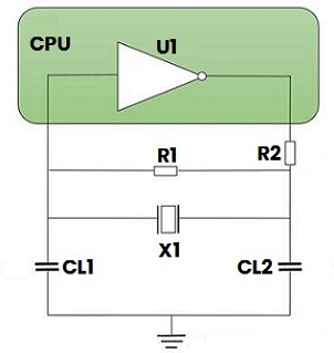
Figure 1: Capacitor Three-point Circuit
U1: Inverting amplifier with large gain.
X1: Crystal, equivalent to the inductor in a capacitor three-point circuit.
CL1, CL2: Matching capacitor, it is the voltage dividing capacitor of the capacitor three-point circuit. And the ground point is the voltage dividing point, it is also the reference point, the input and output are in opposite phases. From the perspective of the parallel resonant circuit, that is, the two ends of the quartz crystal, a positive feedback is formed to ensure that the circuit continues to oscillate. Further more, they will slightly affect the oscillation frequency, mainly used to fine-tune frequency and waveform, and affect amplitude.
R1: Feedback resistor (generally ≥1MΩ), which keeps the inverter in the linear operating area at the beginning of oscillation.
R2: Current-limiting resistor, forming a network with matching capacitors, providing a 180° phase shift, and at the same time limiting the oscillation amplitude to prevent the inverter output from overdriving the crystal oscillator and damaging it.
2. Load Capacitance
The calculation formula:
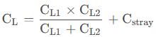
Cstray: It is the shunt capacitance between the two pins of the crystal. It is connected in parallel with the external matching capacitors of the crystal oscillator.
CL1: It indicates the total capacitance from the output pin of the crystal oscillator circuit to ground, including PCB trace capacitance CPCB, chip pin parasitic capacitance CO, and external matching capacitor CL2, that is, CD=CPCB+CO+CL2.
CL2: It indicates the total capacitance from the input pin of the crystal oscillator circuit to ground, including PCB trace capacitance CPCB, chip pin parasitic capacitance CI, and external matching capacitance CL1, that is, CG=CPCB+CI+CL1 (generally we select CL1 and CL2 are the same value, so CG and CD are generally the same). They are in series with the crystal.
Generally, CS is about 1pF, and CI and CO are generally several pF. For details, please refer to the data sheet of the chip or crystal oscillator.
Cic: Pin distribution capacitance and chip internal capacitance (some chips will integrate capacitors inside the chip in order to save Cd and Cg on the PCB).
△C: PCB trace distributed capacitance, generally 3-5pf.
3. Matching Capacitance
In order to maintain the load balance of the crystal, in practical applications, it generally take CL1= CL2, then the following formula can be obtained:

4. Selection Rules
1) Choose NPO/COG high-frequency ceramic capacitors.
2) Try to choose capacitors with small packages (have small parasitic parameters).
3) Because each crystal oscillator has its own characteristics, it is best to select external components according to the values provided by the manufacturer.
4) Within the permitted range, the lower the C1 and C2 values, the better. Although a large C value is beneficial to the stability of the oscillator, it is also increase the start-up time.
5) It is best that the C2 value is greater than the C1 value, which can speed up the start-up of the crystal oscillator when power is turned on.
5. Frequency Offset Calculation
Frequency offset is generally described in units of ppm, which means one part per million, which is 10^-6. If we have a crystal oscillator, its standard frequency scale is 12MHZ, but the actual test value is 11.99998MHZ, so the error is 0.00002MHZ, from which we can get ppm=(0.00002/12)*10^6=1.67 .
Generally, when selecting a crystal oscillator with a better accuracy is good. For example, when the ppm of STM32 chips is <30, it is also acceptable.

 English










