MLCC (multi-layer ceramic capacitor) is a kind of ceramic capacitors, which is widely used in circuits. It is made of ceramic dielectric diaphragms with printed electrodes (internal) stacked in a dislocation manner, and a ceramic chip is formed by one-time high-temperature sintering, and then a metal layer (external electrode) is sealed on both ends of the chip to form a structure similar to a monolith, so it is also called a "monolithic capacitor". As one of the passive components, the main function of the capacitor in the circuit is to store charge, filter AC, bypass, provide tuning and oscillation, and be used for differential and integral circuits. However, the properties of capacitors made of each dielectric material are quite different, and they are used in different fields. Here we mainly look at multilayer ceramic capacitors.
About Multi-layer Ceramic Capacitor (MLCC)
MLCC Process Flow
The Figure 1 shows the structure of ceramic capacitors:
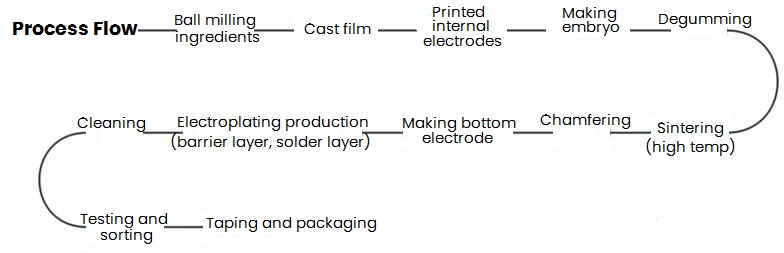
Figure 1: MLCC Process Flow
The main structure of MLCC consists of ceramic dielectric, terminal electrodes, internal electrodes and coating. The internal electrode conductor is generally Ag or AgPd, then prepare a layer of Ni barrier layer (to block the internal Ag/AgPd material and prevent it from reacting with the external Sn or SnPb), and the ceramic medium is generally BaTiO3. In recent years, MLCC products using Cu have also appeared at the end.
a) Material preparation and forming: After the raw materials are calcined, crushed and mixed, they will reach a certain particle fineness. In principle, the finer the particles, the better. Then according to the structural shape of the capacitor, the ceramic dielectric embryo is formed.
b) Sintering: High temperature sinter is performed on the porcelain body to make it into a porcelain body with high mechanical strength and excellent electrical properties. And the necessary temperature is generally above 1300°C. If the processing time is too short, the solid-phase reaction is not complete, which will affect the structure of the embryo body and cause the deterioration of electrical properties, on the contrary, if the holding time is too long, cause the bubbles in blank body to deform, which will also deteriorate the electrical properties.
c) The rest include electrode fabrication, lead welding, coating, encapsulation.
Material Selection
Porcelain powder: it is the decisive factor for the level of product quality, and the use of poor materials will have major hidden dangers of quality accidents. Here give a recommendation, North American medium-temperature sintered porcelain powder and Japanese high-temperature sintered porcelain powder are relatively good.
Inner paste: it is the key factor of product quality level, and the basic requirement of it is matching with porcelain powder material well. If not, the MLCC reliability will be greatly reduced.
Terminal paste: It is also an important factor for the performance of the product. If it is not selected properly, the electrical and mechanical properties of the produced terminal electrode will not good.
History
In 1900, Italian L. Lombardi invented ceramic dielectric capacitors. At the end of the 1930s, it was found that adding titanate to ceramics could double the dielectric constant. Around 1940, people discovered that BaTiO3, the main raw material of the current ceramic capacitor, was insulating, and began to use ceramic capacitors in military electronic equipment that required small size and high precision. To the 1960s, ceramic laminate capacitors were developed as commercial products. By 1970, with the advancement of hybrid ICs, computers, and portable electronic equipment, ceramic capacitors developed rapidly and became an indispensable part of electronic equipment. Now they account for about 70% of the capacitor market.
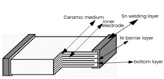
Figure 2: MLCC Internal Structure Diagram
There are several kinds of ceramic materials. Since considering the harmlessness of electronic products, especially lead-free, high dielectric constant PB (lead) has withdrawn from the field of ceramic capacitors, and now TiO2, BaTiO3, CaZrO3 and so on are mainly used. Compared with other capacitors, it has the advantages of small size, large capacity, good heat resistance, suitable for mass production, and low price.
Due to abundant raw materials, simple structure, low price, and wide range of capacitance (generally several PF to hundreds of μF), small loss, and the temperature coefficient of capacitors can be adjusted in a wide range according to requirements.
There are many kinds of ceramic capacitors, and the dimensions vary greatly, from 0402 (about 1×0.5mm) chip capacitors to large power ceramic capacitors.
1) According to the characteristics of the dielectric material used, it can be divided into type I, type II and semiconductor ceramic capacitors; according to the size of reactive power, it can be divided into low-power and high-power ceramic capacitors.
2) According to the working voltage, it can be divided into low-voltage and high-voltage ceramic capacitors.
3) According to the structural shape, it can be divided into disc shape, tube shape, drum shape, bottle shape, cylinder shape, plate shape, lamination, monolith, block shape, pillar type, through-heart type, etc.
Classification
Ceramic capacitors can be mainly divided into two types from the type of medium: class I ceramic capacitors and class II ceramic capacitors.
Class I Ceramic Capacitors
They formerly known as high-frequency ceramic capacitors, refer to capacitors made of ceramic dielectrics with low dielectric loss, high insulation resistance, and a dielectric constant that varies linearly with temperature. It is especially suitable for resonant circuits, and other circuits that require low loss and stable capacitance, or used for temperature compensation.
According to the EIA standard, it is C0G or NP0, etc. This medium is extremely stable, has an low temperature coefficient and does not age. And the loss factor is not affected by voltage, frequency, temperature and time, the dielectric coefficient can reach 400, and the dielectric strength is relatively high. In terms of applications, it is very suitable for high frequency, ultra high frequency and working environment with strict requirements on capacitance and stability. However, its capacitance cannot be made very large (due to the relatively small dielectric coefficient), for example, the capacitance of 1206 surface mount C0G dielectric capacitors is 0.5PF to 0.01μF.
Class Ⅱ Ceramic Capacitors
They are used to be called low frequency ceramic capacitors, which refer to capacitors using ferroelectric ceramics as a medium, so they are also called ferroelectric ceramic capacitors. This type of capacitor has a large specific capacitance, and changes nonlinearly with temperature, so the loss is large. It is often used in electronic equipment for bypassing, coupling, or other circuits that do not require high loss and capacitance stability.
Class II stable ceramic dielectric materials such as X7R and X5R of the EIA standard. The dielectric coefficient of this medium changes greatly with temperature, so it is not suitable for occasions that require high temperature coefficients such as timing and oscillation. However, because its dielectric coefficient can be made very large (up to 1200), the capacitance can be made large, which is suitable for coupling, bypass and filtering that require a higher working environment temperature (X7R: -55~+125°C). For example, the SMD package of 1206 capacitance can reach 10μF or higher.
Available class II ceramic dielectric materials such as Z5U, Y5V, etc. of the EIA standard. The dielectric coefficient of this medium changes greatly with temperature, so it is not suitable for occasions that require high temperature coefficients such as timing and oscillation, but because its dielectric coefficient can be made very large (up to 1000~12000), the capacitance can be made larger, and is suitable for coupling, bypassing and filtering in general working environment (-25~+85°C). For example, 1206 surface mount Z5U and Y5V dielectric capacitors can even reach 100μF, which can be used to replace tantalum electrolytic capacitors in a sense.
What is the temperature coefficient represented by C0G?
C - The effective figure of the temperature coefficient of capacitance is 0 ppm/℃.
0 - The multiplication factor of significant figures is -1.
G - ±30ppm tolerance over temperature
NPO is the abbreviation of negative-positive-zero, used to represent the temperature characteristics. It shows that the capacitance temperature characteristic of NPO is very good, and the value does not drift with the positive and negative temperature changes. It can be seen from the above that C0G is the one with the best temperature stability among Class I ceramics, and the temperature characteristic is approximately 0. Actually, C0G is the same as NPO, but it is just two representation methods of two standards (of course, C0K, C0J, etc. with smaller capacitance and slightly worse precision are also NPO capacitors). In addition, the capacitance and dielectric loss of NPO capacitors vary with frequency depending on the packaging form, and the frequency characteristics of large package sizes are better than those of small package sizes.
What is the temperature coefficient represented by X7R?
X - the capacitor can work at -55℃
7 - the capacitor can work at +125℃
R - the capacitance change with temperature is ±15%
Similarly, the normal operating temperature range of Y5V is -30°C to +85°C, and the corresponding capacitance change is +22 to -82%; while the normal operating temperature range of Z5U is +10°C to +85°C, the related capacitance change is +22~-56%.
MLCC Features
Conventional Electrical Properties
(1) Capacity and error: the maximum deviation range allowed between the actual capacitance and the nominal capacitance. The capacity errors generally used are: J grade ±5%, K grade ±10%, M grade ±20%. Precision capacitors have smaller allowable errors, while electrolytic capacitors have larger errors, and they use different error levels. Commonly used capacitors have the same precision rating as resistors. Indicated by letters: Grade D—±0.5%, Grade F—±1%, Grade G—±2%, Grade J—±5%, Grade K—±10%, Grade M—±20%.
(2) Rated operating voltage: The maximum DC voltage that a capacitor can withstand in a circuit that can work stably and reliably for a long time, also known as withstand voltage. For devices with the same structure, medium, and capacity, the higher the withstand voltage, the larger the volume.
(3) Temperature coefficient: Within a certain range, the relative change value of capacitance when the temperature changes by 1°C. The smaller the temperature coefficient, the better.
(4) Insulation resistance (IR): It is used to indicate the size of leakage. Generally, a small-capacity capacitor has a large insulation resistance, in the hundreds of megaohms or several gigaohms. The insulation resistance of electrolytic capacitors is generally small. Relatively speaking, the larger the insulation resistance, the better, and the smaller the leakage. General C0G >1000ΩF, while X7R and Y5V >500ΩF.
(5) Loss (DF): Under the action of an electric field, the energy consumed by the capacitor to generate heat per unit time. These losses mainly come from dielectric loss and metal loss. It is usually expressed by the loss tangent value. The most standard writing method for loss: use percentage writing method, for example: COG requires <0.015%, X7R<2.5%, Y5V<3.5%; in reality, COG type <10*10-4, X7R type<250*10-4, Y5V type<500 *10-4.
(6) Frequency characteristics: The nature of the electrical parameters of the capacitor changing with the frequency of the electric field. For capacitors working under high frequency conditions, since the dielectric constant is smaller at high frequencies than at low frequencies, the capacitance also decreases accordingly, and losses also increase with frequency. In addition, when working at high frequency, the distributed parameters of the capacitor, such as the resistance of the electrode, the resistance between the lead and the electrode, the self-inductance of the electrode, and the inductance of the lead, will affect the performance of the capacitor. All of these limit the frequency of capacitors.
Different types of capacitors have different maximum operating frequencies. Small mica capacitors are within 250MHZ; disc type ceramic capacitors are 300MHZ; round tube type ceramic capacitors are 200MHZ; small paper capacitors are 80MHZ; medium paper capacitors are only 8MHZ.
Important Parameters
TCC: Temperature capacity characteristics, note that the capacity stability near normal temperature is different for X7R products.
ESR: Equivalent series resistance
ESL: Equivalent series inductance
Q value: It is a synthesis of DF, ESR, and ESL, and it is more concerned about high-frequency circuits.
Among them, ESR (Res) is mainly composed of four aspects: dielectric layer resistance, internal electrode layer resistance, contact surface resistance and terminal electrode resistance, And each contact surface resistance includes terminal electrode and internal electrode contact, contact between different terminal electrode plating layers, etc. In addition, Res is more sensitive to frequency and increases with frequency, because:
1) Contact resistance - The gap-like crack formed by the contact between electrodes is capacitive impedance (Z=1/(2*pi*f*C)), which causes Res to decrease with the increase of frequency at the beginning.
2) Skin effect - Due to the skin effect of the inner electrode and the terminal electrode, the impedance increases with the increase of the frequency, which will eventually offset the influence of the ESR drop caused by the contact resistance.
3) Dielectric polarization - With the orientation of the polarization in the dielectric, a large amount of energy is stored, thus exhibiting an increase in impedance with frequency.
The ESL of chip ceramic capacitors is similar to that of chip solid tantalum capacitors. They are both SMD devices and have relatively small ESL. However, due to the internal lead structure, the ESL of ceramic chips is much smaller than that of tantalum capacitors. An approximate formula can be used:
For calculation, such as 1206 package, then L=12, W=6. Although ESL is related to capacity, relatively speaking, the change is very small and can be ignored.
MLCC Advantages
(1) Large capacity range: Compared with single-layer capacitors, MLCC's stacking technology makes it have a larger capacitance.
(2) Ultra-small size: The continuous upgrading of smart phones and tablets and other products has brought about a trend of thinner and thinner products, and there is an urgent need to reduce the size of the applied capacitors. At present, the product size is developing towards 0201 and 01005.
(3) Low equivalent series resistance: The ESR of MLCC is generally only a few milliohms to tens of milliohms, which is several orders of magnitude different from other types of capacitors. Smaller ESR means that the components dissipate less heat during operation, so that most of the energy is used for the operation of electronic equipment instead of being consumed in the form of heat energy, which improves the operating efficiency and also increases the service life.
(4) High rated voltage: The high-temperature sintering makes the structure dense. Compared with capacitors made of other materials, it has better withstand voltage characteristics and wider voltage series, which can meet the needs of different circuits.
(5) Good high-frequency characteristics: The development of materials makes MLCC have suitable ceramic materials in each frequency band to achieve low ESR and impedance, and it has good properties in high-frequency circuits.
(6) Non-polarity: Due to the non-polarity, it is more convenient to assemble and use.
Working Failure
The failure causes of MLCC are divided into internal &external factors.
Internal Factors
1) Voids
The main factors leading to it are organic or inorganic pollution in the ceramic powder, improper control of the sintering process, etc, which can easily lead to leakage, and the leakage will cause local heating inside the device, further reducing the insulation performance of the ceramic dielectric and resulting in more leakage. With his process occurs cyclically and continues to deteriorate, in severe cases, it will lead to serious consequences such as cracking, explosion, and even burning.
2) Firing Crack
Firing cracks often originate from one end electrode and propagate along the vertical direction. The main reason is related to the cooling rate during the sintering process, and the cracks and hazards are similar to the voids.
3) Delamination
The MLCC sinter is the co-firing of multilayer material stacks, and the working temperature can be as high as 1000°C or more. Inadequate interlayer bonding, volatilization of internal pollutants, and improper control of the process may lead to delamination. It is also similar to the hazards of voids and cracks, and is an inherent defect of multilayer ceramic capacitors.
External Factors
1) Thermal Crack
It is mainly due to the temperature shock of the device during soldering, especially wave soldering. And improper repair is also an important reason for it.
2) Flex Crack
MLCCs are characterized by their ability to withstand large compressive stresses, but their ability to resist bending is relatively poor. Any operation that may cause bending deformation during device assembly may lead to cracking of the device. Common stress sources include: patch alignment, circulation process, through-hole insertion, circuit testing, single board segmentation, circuit board installation, positioning riveting, screw installation, etc. It is also the type of defect that actually occurs the most.
MLCC Developing Trend
The improvement of downstream demand drives the upgrade of upstream products. In the future, the upgrade of MLCC products in the field of automobiles and mobile phones is mainly in:
(1) Miniaturization: Under the general trend of thinner and lighter smartphones, the average occupied volume of components is increasing, and the demand for capacity is increasing during the upgrading of mobile phone functions. At present, miniaturized MLCCs such as 0201 and 01005 are popular for high-end flagship mobile phones.
(2) High voltage and high reliability: The automotive field has high requirements for product safety, and the reliability of MlCC often has a great impact on the stability of body electronics; the average power of the automotive electronics field is much higher than that of mobile phones to have a greater demand. For large-scale systems such as power supply systems, satellites, and radars, their work requires higher voltages and currents. The application of MLCCs in this field requires components to maintain high reliability of the system at higher operating voltages.
(3) High-frequency and high-temperature working conditions: The wireless frequency in the 5G era has entered the millimeter-wave frequency band. The improvement of power and performance requirements requires MLCC to work at high frequency and high temperature. In addition, the working temperature of commonly used MLCC is about 125°C, and the new type reaches 260°C.
(4) High capacity: Due to the advantages of non-polarity and high reliability, MLCC has become the best choice to replace tantalum capacitors. For this reason, new materials and processing technologies are constantly developing in the direction of high capacity.

 English










