Ground resistance measurement is a crucial part of electrical safety, as high resistance can lead to decreased performance of electrical equipment and even cause electrical fires. Therefore, understanding and mastering the correct methods for measuring ground resistance is essential for ensuring the safety of personnel and assets.
Ground Resistance Basic
What is Ground Resistance?
Ground resistance refers to the resistance encountered when current flows from the grounding electrode into the earth. The value of ground resistance depends on factors such as the shape, size, material of the grounding electrode, and the resistivity of the surrounding soil. It is an important parameter in electrical systems to ensure proper grounding and safety. And Ground resistance is measured to ensure that this connection is effective and that there is a low-resistance path to dissipate fault currents safely into the ground, and the value is usually expressed in ohms (Ω). For the lowest acceptable reference values of ground resistance, in power systems, working ground resistance should not exceed 4Ω; protective ground resistance should not exceed 4Ω; repeated ground resistance should not exceed 10Ω; for lightning protection, independent lightning rods should not exceed 10Ω; and finally for substation valve-type lightning arresters, it should not exceed 5Ω.
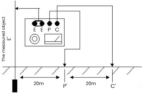
Figure 1: Ground Resistance Measuring
What is a Good Ground Resistance?
A good ground resistance typically refers to an acceptable resistance value measured between an electrical grounding system and the earth. The specific value considered "good" can vary depending on the application, local regulations, and standards. However, here are some general guidelines:
1. Industrial and Commercial Installations: For most industrial and commercial installations, a ground resistance of 1 ohm or less is often considered good. Some standards may allow up to 5 ohms, but lower values are preferred for better safety and performance.
2. Sensitive Electronic Equipment: In environments where sensitive electronic equipment is used (such as data centers, telecommunications facilities, or medical facilities), ground resistance requirements may be more stringent. Values as low as 0.5 ohms or even lower are often specified to minimize electrical noise and ensure reliable operation.
3. Residential Installations: In residential settings, a ground resistance of 5 ohms or less is typically acceptable according to many standards. However, lower resistance values can provide better protection against electrical faults and lightning strikes.
Ideally, the ground resistance should be of zero ohms but there is no standard ground resistance threshold or value that is being followed. So it's important to note that the actual acceptable ground resistance may be specified in local electrical codes, building regulations, or by equipment manufacturers. Factors such as soil type, moisture content, and the type and depth of grounding electrodes used can influence the measured ground resistance.
Regular testing and maintenance of grounding systems are crucial to ensure that ground resistance remains within acceptable limits. Periodic measurements using specialized instruments help verify the integrity of the grounding system and ensure continued safety and reliability of electrical installations.
Standards for Ground Resistance Testing
Ground resistance testing is an essential procedure to ensure the effectiveness of grounding systems in electrical installations. The standards for ground resistance testing generally depend on the region or country where the testing is being conducted. However, some widely recognized standards include:
1. Main Standards
2) IEEE 81: IEEE Guide for Measuring Earth Resistivity, Ground Impedance, and Earth Surface Potentials of a Ground System.
2) IEEE 142: IEEE Recommended Practice for Grounding of Industrial and Commercial Power Systems (Green Book).
3) ANSI/IEEE 80: IEEE Guide for Safety in AC Substation Grounding.
4) IEC 61557-5: Electrical safety in low voltage distribution systems up to 1kV AC and 1.5 kV DC – Equipment for testing, measuring or monitoring of protective measures – Part 5: Resistance to earth.
5) NFPA 70: National Electrical Code (NEC), specifically Articles 250.52, 250.53, and 250.56, which provide guidelines for grounding systems.
2. Key Standards and Recommendations
1) Measurement Methods: These standards specify the methods for measuring ground resistance using instruments such as earth ground testers (clamp-on or stake-type), fall-of-potential testers, and selective ground testers.
2) Acceptable Resistance Values: Typically, the acceptable ground resistance value depends on the specific application and the standards or local regulations in place. For example, in some cases, a ground resistance of 25 ohms or less might be acceptable, but for sensitive electronic equipment or lightning protection systems, much lower values (e.g., 5 ohms or less) might be required.
3) Testing Frequency: Standards also provide guidance on how often ground resistance testing should be performed. This can vary from periodic testing (e.g., annually or biennially) to testing after significant changes or additions to the electrical system.
4) Safety Considerations: Standards emphasize safety precautions for personnel conducting ground resistance testing, including proper grounding of test instruments, avoiding hazards associated with electrical shock, and ensuring proper personal protective equipment.
Although there are overarching international standards like those from IEEE and IEC, adherence to local regulations and codes is crucial for conducting ground resistance testing correctly and safely.
Measuring Tips
A low ground resistance is desirable because it helps to ensure that fault currents will flow effectively to the ground, facilitating proper operation of protective devices like fuses and circuit breakers. High ground resistance can lead to ineffective grounding, potentially causing electrical hazards such as electric shock, equipment damage, or even fires.
Ground resistance is typically measured using specialized instruments designed for this purpose. The measurement is influenced by factors such as the type of soil, moisture content, depth of the grounding electrode, and the quality of the connection between the electrode and the grounding system.
1. Choose the right ground resistance measuring instrument: Measuring ground resistance requires the use of specialized instruments such as ground resistance testers. When selecting a measuring instrument, ensure its accuracy, reliability, and compliance with local standards and regulations.
2. Determine the position of the grounding electrode: The grounding electrode serves as the medium through which current flows into the earth, making the precise positioning crucial for accurate measurements. Typically, the grounding electrode needs to be inserted into moist soil to reduce resistance.
3. Measure the resistance between the grounding electrode and the earth: Connect the grounding electrode to the earth and use a ground resistance tester for measurement. During measurement, avoid contact between the equipment and the human body to prevent electric shock.
4. Analyze the measurement results: Based on the resistance value obtained, assess whether the grounding system meets requirements. Generally, a lower ground resistance value indicates better performance of the grounding system.
Introduction of Ground Resistance Measuring Methods
1. Use a Ground Resistance Tester
Operation Methods
The operation method is as follows:
(1) First, according to regulations, bury the auxiliary ground probe and connecting wires provided with the instrument (C - connected to a 40m long wire, P - connected to a 20m short wire, E - connected to the grounding electrode).
(2) Disconnect the connection between the ground probe being measured and the protected electrical equipment.
(3) Place the instrument flat and select the appropriate scale.
(4) Rock the instrument to adjust the balance indicator, so that the pointer points to zero.
(5) Try to operate the instrument at the rated speed for reading, and if there is interference from ground current, it is also possible to slightly adjust the speed to zero the instrument before taking readings.
(6) Every time the scale is changed, the measurement dial must be readjusted to zero the instrument.
Case Study
In this section, we will detail how to correctly measure ground resistance through a practical case study. The case study involves a commercial building where we need to measure the resistance of its power system's grounding device.
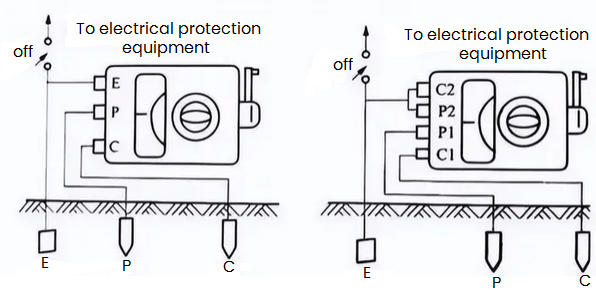
Figure 2: Ground Resistance Measuring Case Study
1) Measurement Steps
a. Preparation: Firstly, we chose a ground resistance tester that meets the standards. Then, we selected a suitable location for the grounding electrode and ensured that the soil in that location was moist.
b. Implementation of measurement: We inserted the grounding electrode into the preselected location and used the tester to measure the resistance between the grounding electrode and the earth. During the measurement process, we strictly followed the operating procedures to avoid contact between the equipment and the human body.
c. Analysis of results: Based on the measured resistance value, we found that the building's grounding system performs well and meets safety standards.
2) Notes: Precautions For Measuring the Ground Resistance
a. Before measurement, first insert the two probing needles into the ground: connect the grounding electrode E, the potential probe P, and the current probe C in a straight line with a distance of 20 meters between them. Place P between E and C. Then, use dedicated wires to connect E, P, and C respectively to the corresponding terminals on the instrument.
b. Preparation before measurement: Disconnect the equipment from the grounding line before use. Place the instrument flat and perform mechanical zeroing.
c. Wiring for grounding resistance measurement: First, insert the current probe C into the soil at a depth of about 40 cm, 40 meters away from the ground electrode E to be measured. Then, insert the potential probe P between the ground electrode E and the current probe C, with all three in a straight line and spaced 20 meters apart. Finally, connect E to the E terminal of the instrument using a wire, connect the potential probe P to the P terminal of the instrument, and connect the current probe C to the C terminal of the instrument.
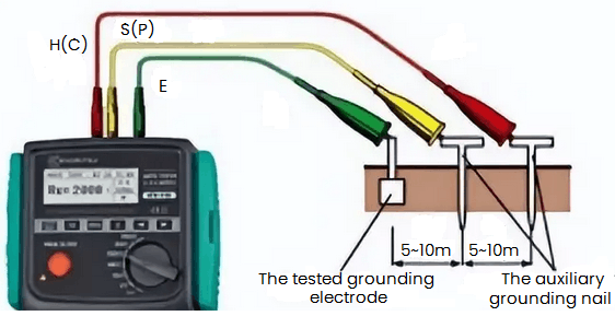
Figure 3: Probe Connection Methods
2. Two-line Method
(1) Conditions
There must be a well-grounded ground, such as PEN. The measured result is the sum of the resistances of the measured and known grounds. If the ground is known to be much smaller than the resistance of the measured ground, the measurement result can be used as the result of the measured ground.
(2) Application
Areas with dense buildings or concrete floors cannot be used for ground piles.
(3) Wiring
E ES is connected to the measured ground, H S is connected to the known ground.
3. Three-line Method
(1) Conditions
There must be two ground rods: an auxiliary ground and a detection electrode. The distance between each ground electrode is not less than 20 meters.
(2) Principle
The current is added between the auxiliary ground and the measured ground to measure the voltage drop between the measured ground and the detection electrode. The measurement results include the resistance of the cable itself.
(3) Application
Grounding, grounding at construction sites and grounding lightning rod QPZ.
(4) Wiring
S is connected to the detection electrode, H is connected to the auxiliary ground, and E and ES are connected to the measured ground.
4. Four-line Method
The four-wire method is basically the same as the three-wire method. It replaces the three-line method when measuring the low ground resistance and eliminating the effect of the measurement cable resistance on the measurement result. E and ES must be connected directly to the ground to be measured separately. This method is the most accurate of all ground resistance measurement methods.
5. Single Clamp Method
(1) Conditions
Measure the ground resistance of each ground point in a multi-point ground. Do not disconnect the ground connection to prevent danger.
(2) Application
Multi-point grounding. Do not disconnect. Measure the resistance of each ground point.
(3) Wiring
Use a current clamp to monitor the current at the measured ground point.
6. Double Clamp Method
(1) Conditions
Multi-point grounding without measuring auxiliary ground stakes, measuring single grounding.
(2) Wiring
Use the current clamp specified by the manufacturer to connect to the corresponding socket, and clamp the two clamps on the ground conductor. The distance between the two clamps should be greater than 0.25 meters.
Conclusion
In summary, ground resistance is a crucial electrical parameter that ensures the safety and proper functioning of electrical systems by providing a low-resistance path to dissipate fault currents into the earth. There are various methods for measuring ground resistance, and the choice of method depends on the characteristics of the grounding system, the measurement environment, and the required accuracy. The methods mentioned above are commonly used and applicable to a wide range of scenarios, offering simplicity and efficient measurement capabilities. However, for specialized applications, more professional equipment may be necessary. When performing ground resistance measurements, consider all relevant factors and select the most suitable method to obtain accurate results.
You May Also Like:

 English










