Basic Info
What is a resistor?
A resistor is a passive two-terminal electrical component according to Ohm's law. It can limit the current in the circuit, reduce voltage, and adjust resistance value. A resistors is generally composed of a resistance element, leads, and a fixed device. The resistance element, made of conductive material, comes in different shapes and sizes, with the different material and length depending on the resistance value and power rating of the resistor. The function of the leads is to connect the resistance element to other components in the circuit. The fixed device can be used to secure the resistor, enhancing its structural stability. Various types of resistors are widely used in different fields such as electronic devices, communication equipment, instrumentation, automotive electronics, home appliances, and robotics. In electronic circuits, they are represented by specific symbols, but how are they represented on a multimeter?
What is a multimeter?
A multimeter is a measuring instrument that combines a voltmeter, ammeter, and ohmmeter into one device, commonly used to measure resistance, current, voltage, capacitance, frequency, and other basic electrical quantities. It consists of a meter head, dial, knob, scale, and cables. By adjusting the knob, the multimeter can be set to measure voltage, current, or resistance. The multimeter has a wide range of measurement capabilities to meet the requirements of different circuits.
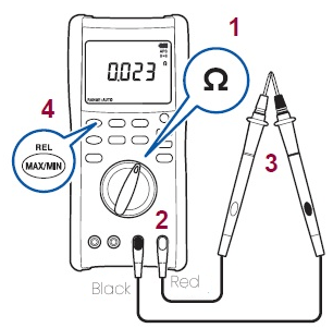
Figure 1: Measuring Resistance with a Multimeter
When measuring resistance with a multimeter, you first need to rotate the meter head to the resistance measurement position, which is usually marked with the Ω (ohm symbol). The resistance measurement range of a multimeter has multiple gears that can be manually adjusted, with different gears suitable for measuring different ranges of resistance. When selecting the measurement range, it is generally necessary to first roughly estimate the order of magnitude of the resistance to be measured and choose a range that is close to it. If the resistance value is relatively small, it is recommended to start with a smaller range and then adjust according to the meter head indication and the result. It is important to note that before using a multimeter to measure resistance, you should check whether the test circuit is normal and whether the resistor to be measured exists independently, and disconnect the connecting wires at both ends of the resistor.
Judging the resistance reading requires considering the selected measurement range and the meter head indication value. Generally, you need to pay attention to the number of digits after the decimal point and the most significant digit of the resistance. If you cannot determine the accuracy of the measurement result, it is recommended to recheck the test circuit. In summary, when using a multimeter to measure resistance, it is very important to set the measurement range correctly and follow the standard operating procedures. If you want to get more details about it, you can read the following examples introduced in this article.
Recognizing Resistor Symbols
Detailed Description of Resistor Symbols
A resistor is commonly represented by "R". In electronic circuits, the resistor symbol varies slightly depending on the standard being used, but the most common symbol for a resistor in circuit diagrams is a zigzag line. Here's how it typically looks:
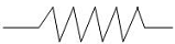
Figure 2: Standard Resistor Symbol
There are different types of resistors, and of course they have different circuit symbols to represent them. Several common types of resistors are Fixed Resistors, Variable Resistors, Special-Purpose Resistors, Network Resistors, Surface Mount Device (SMD) Resistors, Current Sense Resistors, etc. Each of these resistor types can be represented by a specific symbol in circuit diagrams, but the basic zigzag or rectangular symbol is often used generically for fixed resistors, while variable resistors have their own distinct symbols that indicate the presence of a moving element or control. If you have more interests of resistor symbols, you can read How to Distinguish a Resistor Symbol in Circuits?
Use Multimeter to Find Resistor Symbols
How to find the resistor symbol on the multimeter?
To find the resistor symbol on a multimeter, you first need to determine whether your multimeter has the function of measuring resistance. Not all multimeters have this feature, but many modern digital multimeters (DMM) can measure resistance.
Resistor Symbol on Multimeter:
The resistance symbol on a multimeter is typically represented by "Ω," which is the symbol for the unit of resistance, pronounced "ohm." In addition, multimeters provide different resistance ranges to accommodate measurements of various resistance values. These ranges include:
Ω : Ohm range, used for measuring smaller resistance values, such as resistances in the range of hundreds or thousands of ohms.
KΩ: Kilo-ohm range, used for measuring slightly larger resistance values, ranging from hundreds of kilo-ohms to even mega-ohms.
MΩ: Mega-ohm range, used for measuring very large resistance values, such as resistances in the hundreds of mega-ohms.
In digital multimeters, these symbols are displayed directly on their surface, making it convenient for users to select the appropriate range for their measurements.
How to measure resistors with a multimeter?
When using a multimeter to measure resistance, you need to follow certain steps and notes to ensure the accuracy and safety of the measurement. Here are some key points and steps:
1. Select the correct measurement range:
Multimeters usually have multiple resistance measurement ranges, such as 200Ω, 2kΩ, 20kΩ, etc. Select a range that is slightly higher than the resistance value you want to measure to obtain accurate measurement results.
2. Connect the test leads:
Connect the red test lead of the multimeter to the positive terminal (usually marked with the Ω symbol) in the measurement lead jacks, and connect the black test lead to the negative terminal (usually marked with the COM symbol).
3. Measure resistance:
Connect the other ends of the two test leads to the two ends of the resistance you want to measure. Make sure there is no looseness or poor contact between the leads and the circuit.
4. Read the measurement results:
When the measurement lead connection is stable, the multimeter will display the measured resistance value. You can read the measurement results on the digital display of the multimeter.
5. Notes:
1) Before using the multimeter, have mechanical zero adjustment to ensure that the pointer points to the zero voltage or zero current position.
2) During the measurement process, avoid touching the metal part of the test lead with your hands to ensure measurement accuracy and personal safety.
3) When measuring, avoid changing gears during the measurement process, especially when measuring high voltage or high current, to prevent damage to the multimeter.
4) The multimeter should be placed horizontally to avoid errors, and pay attention to avoid the influence of external magnetic fields on the multimeter.
The resistor symbol on the FLUKE Multimeter
1. Where you should connect?
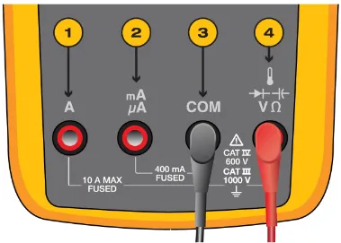
Figure 3: Digital multimeter jacks (Image from FLUKE)
④ : Red test lead input for
Measurements for voltage (V), resistance(Ω), diode (arrow plus symbol), capacitance (other symbol), frequency, duty cycle and, if available, temperature. Also accepts red clamp lead when using Halle Effect-style current clamps.
2. To measure resistance:
1) Turn the rotary switch to resistance mode. Ensure that power is removed from the circuit under test.
2) Connect the red test lead to measurement mode and the black test lead to the COM terminal as shown.
3) Touch the probes to the desired circuit test points to measure resistance.
4) Read the measured resistance on the display.
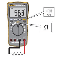
Figure 4: Resistance Measurement
Turn on/off Test:
After selecting the resistance mode, press the button again to activate the continuity beeper. If the resistance is less than 70Ω, the beeper will sound continuously, indicating a short circuit.
Tips that should be noted when measuring resistors with multimeters
When using a multimeter to measure a resistor, it is essential to follow certain precautions and considerations to ensure accurate measurements and prevent damage to the multimeter or the resistor being tested. Here are some key points to note when using a multimeter to measure a resistor:
1. Ensure the resistor is disconnected: Before measuring the resistor, ensure that it is disconnected from the circuit to prevent parallel paths that could affect the measurement accuracy.
2. Select the resistance setting: Set the multimeter to the resistance (ohms) measurement mode. Choose an appropriate range on the multimeter that is slightly higher than the expected resistance value to obtain accurate measurements.
3. Identify the resistor tolerance: Be aware of the resistor's tolerance value to determine whether the measured resistance falls within the acceptable range.
4. Probe placement: Connect the multimeter probes across the resistor terminals. Ensure that the probes make good contact with the resistor leads or terminals for accurate readings.
5. Stable contact: Maintain stable contact between the probes and the resistor to prevent fluctuations in the measured resistance value due to loose connections.
6. Avoid excessive force: Do not apply excessive force when making contact with the resistor to avoid damaging the resistor or altering its resistance value.
7. Watch for residual charge: Ensure that the resistor does not hold any residual charge that could affect the measurement. Discharge the resistor if necessary before measuring.
8. Read and record the measurement: Take note of the measured resistance value displayed on the multimeter. Record the reading for future reference or troubleshooting.
9. Compare with expected value: Compare the measured resistance value with the expected or nominal resistance value of the resistor to verify its condition and integrity.
10. Repeat for accuracy: If needed, repeat the measurement a few times to ensure consistency and accuracy of the readings.
By following these tips when using a multimeter to measure a resistor, you can obtain reliable and accurate resistance measurements while protecting both the multimeter and the resistor under test. If you encounter any unexpected readings or have further questions about measuring resistors with a multimeter, feel free to contact us.
You May Also Like:
What Are Resistors in Your Common Sense?
Current Sensing Resistor: Basics, Calculation, Parameters, Design Tips
What is Film Resistor? Thin & Thick Resistor Manufacturing Details
RLC Circuit - Basics, Calculation, Oscillation Explained
Resistor Selection According to Three Aspects

 English










