Current sense resistors are used to detect and convert current to a measured output voltage. They help improve system efficiency and reduce losses due to their high measurement accuracy compared to other technologies. These devices feature very low resistance values, and therefore, cause only an insignificant voltage drop of 10 to 130mV in the applications.
Current Sense Resistors Basic
What is Current Sense Resistor?
Current sense resistor is often required in many general electronics applications for monitoring and control applications. For example, the battery charger circuit requires it to determine the current from the perspective of the driver and controller. Different types of current sense resistors have different current sensing technologies and are used to measure or detect current. The most common and cost-effective solution for current sensing is a shunt current sensor, also known as a current sense resistor.
Current sense resistors is similar to a regular resistor but has a very low resistance rating and a high power rating. These shunt resistors of known resistance (R) are placed in the current conduction path to allow the entire current to be measured (I) to flow through the resistor.
Working Principle
In electronics, shunting means giving a different path to the circuit, and the current sense resistor does the same, creating a very low path for the current to flow from one part of the circuit to another part. In this path, the amount of current flowing through the circuit can be measured every time it passes through a low-resistance area, regardless of the current.
By measuring the voltage drop (V) across the resistor, and using Ohm's law, we can calculate the amount of current flowing through the circuit.
V=IxR
Where V is the voltage drop across the current sense resistor, I is the current flow rate, and R is the resistance value in ohms. So if the resistance is static, for example, 1ohm in all cases, V depends on I.
Parameters Selection
Current sense resistors are a special type of resistor, which are different from the resistors traditionally used in electronic circuits. General resistors are used for very low operating currents, usually at standard ambient temperatures, such as 0-85°C. However, the current sense resistor has a wide temperature coefficient range due to the large current flowing through it.
So the main difference between standard resistors and current sense resistors is the temperature coefficient of the thermal electromotive force. In a normal resistor, the thermal electromotive force is ignored, but for a current sensing resistor, two different conductive materials will produce a variable voltage depending on the temperature. Therefore, the selection of component materials for current sensing resistors is important. Most of the time, manganese-copper (-3.0uV/oC thermal EMF with excellent temperature coefficient range) is used to make current sense resistors.
Below are several important parameters to consider when selecting a current sense resistor.
1. Resistance value and rated power
The resistance value is an important parameter for the current sense resistor, which determines how much the voltage will drop during the flow of current from the perspective of the current sense amplifier (according to its maximum current and maximum input voltage). However, larger values affect the resistor's power rating and increase heat dissipation.
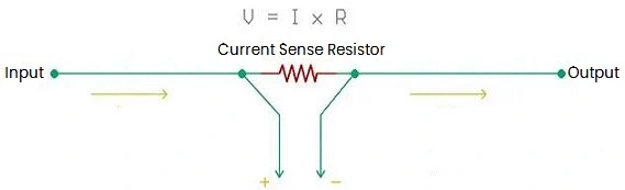
Figure 1: Current Sense Resistor Circuit Diagram
The above circuit shows how to place a current sense resistor in the current carrying path and how to use a current sense amplifier to calculate the voltage drop across the resistor.
The power dissipation of the resistor can be determined using the following formula:
P=VxI
Where V is the voltage and I is the current. Since the voltage drop across the resistor can be determined using Ohm's law, The power dissipation can be determined by:
P=I2R
Therefore, a current sense resistor with a smaller value will generate less heat and negate the use of an additional heat sink.
The relative resistance values are typically milliohm ratings, which are usually chosen and result in less power dissipation in large currents. The resistors will have lower wattage and will be very small in size, contributing to a smaller PCB. Further more, the power dissipated in the shunt resistor can also be determined using the resistor's PCR value. Here PCR stands for Resistor Power Coefficient (ppm/W), which represents the different power consumption values of resistors with different resistance values.
2. Tolerance
The current sense resistor is not an ideal resistor. Therefore, the tolerance of it is an important parameter that affects the sensing accuracy. Generally, common resistors have tolerances of 10%, 5% or even 1%. So a resistor with a rating of 10 ohms and a tolerance of 10% will have values from 9Ω to 11Ω. During normal operation, this value changes due to ambient temperature and other additional dependencies. However, in most applications, resistor tolerance is not important, but for applications highly dependent on the sensed values, tolerance becomes a critical parameter to consider. Current sense resistor tolerances range from 1% to 0.1%, and how much accuracy is required depends entirely on the application requirements and this parameter.
3. Temperature coefficient
A resistor's TCR, or temperature coefficient (ppm / °C), is the parameter that determines how much a temperature change in a resistor changes its resistance. It is an important parameter in current sense resistor applications and is not important for general purpose resistors. And it needs to be very low because the power dissipation may be greater due to the larger current which increases the resistor temperature, and may provide readings with errors.
The TCR value depends on the material used as the resistive element, the tolerance, the power rating, and the physical dimensions of the resistor. There are a variety of shunt resistors using very low TCR values due to the use of metal foil components as the resistive material.
Placement of Current Sense Resistor
There are mainly two types:
1. In High-side
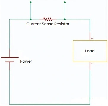
Figure 2: Current Sense Resistor In High-side
In this method, the current sense resistor is placed on the high side of the load. This placement is widely used and often requires a differential amplifier to sense the actual current flowing through the resistor.
2. In Low-side
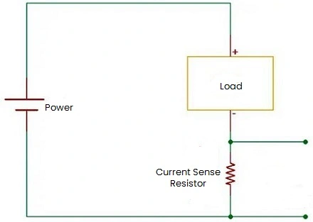
Figure 3: Current Sense Resistor In Low-side
In this method, the current sense resistor is placed on the low side of the load. This layout cancels out the load ground, and it is often difficult to determine the short circuit condition of the load. And this will create a voltage drop across the resistor, which can be used to sense the current flowing through the load and the resistor.
Current Sensing Resistor Circuit Design Ideas
1. DC Power Supply
The figure below shows the current detection circuit and the surge current protection circuit in a simple power supply. In these circuits, a current sense resistor is placed on the load current supply line. And the current is measured by measuring the voltage across it using an op amp or control IC.
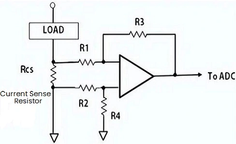
Figure 4: Current Detection Circuit Example (Load)
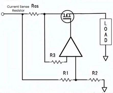
Figure 5: Surge Current Protection Circuit Example
2. DC-DC Converter
For example, in the DC-DC converter below, in order to monitor the output, the current sense resistor is placed outside the converter. To minimize power loss in the resistor, very low resistance are selected.
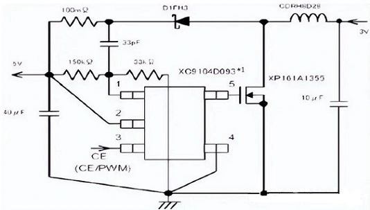
Figure 6: Current Detection Circuit Example (in DC-DC Converter)
3. Motor Drive Circuit
There are two purposes of using a current sense circuit in a motor drive circuit, as shown in the figure below. In order to protect the circuit and detect the phase of the motor drive voltage, additionally, to save space, very low resistance current sense resistor is used in the phase detection circuit.
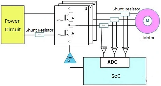
Figure 7: Motor Driver Circuit
4. MPPT-based Solar Charge Controller Circuit
The following is an example of selecting a current sense resistor for an MPPT based solar charge controller circuit through which the battery being charged is the load.
Where, the load is connected using shunt resistor R6, and it determines the charging current, which means the voltage drop across R6 will remain constant in any case. Since V=Ix R, if R remains the same, so does the V, and the driver will vary the charging current.
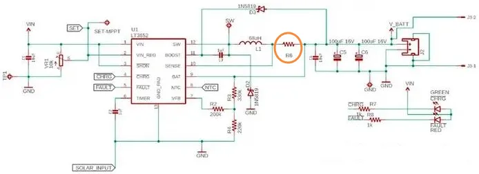
Figure 8: Solar Charge Controller Circuit Based on MPPT Use Current Sense Resistor
To select a current sense resistor, three conditions need to be considered:
1) The driver IC LT3652 will use constant voltage.
2) The maximum charging current that needs to be transmitted to the battery through the resistor.
3) Since it is charge control, the tolerance may be 1%.
According to the LT3652 datasheet, the pin will use a constant sense voltage of 100mV (0.1V). In addition, the maximum charging current supported by the LT3652 is 2A. Therefore, the current sense resistor value needs to meet the formula R=V/I, so the calculated value will be 0.1V / 2A = 0.05Ω or 50mΩ.
The resistor needs to have a power rating of P=I2R or P= 22 x 0.05 = 0.2W. The closing value of the current sense resistor is 50mΩ, and 1% of rating, that is 0.25W.
Tips for Measuring Current
1. Choose the Best Ohm Value
It is a matter of balance. If it's too high, you waste power, generate too much heat, and lose voltage regulation. If it is too low, the induced voltage will decrease accordingly, so noise and resolution issues will limit accurate measurements.
2. Choose the Correct Rated Power
Power rating is sometimes a function of PCB layout design as well as component selection.
3. Select Resistor Technology
Different applications require different resistor technologies. Many current sense resistors fall into the bulk metal technology category, and this means that the element is a self-supporting piece of resistive metal alloy.
4. Optimize PCB Design
The PCB trace design around the current sense resistor is usually more critical to performance than a regular resistor.
5. Manage Heat
Whether your design requires a resistor with a very high rating or a relatively small temperature rise, it is important to understand how the heat will be removed and where it will flow.
6. Allow Current Surges
Typically, the design must accommodate moderately high surges above the maximum current that needs to be accurately measured.
7. High Temperature Derating
As with any resistor, if the ambient temperature is higher than the rated temperature, power derating must be applied.
8. Understand Thermoelectromotive Force
Thermoelectric voltages may need to be considered when shunting with metal components with high heat dissipation and low induced voltages.
9. Reduce Induction Errors
The combination of high current paths and low signal voltages makes current sense resistor circuits particularly susceptible to sensing errors.
10. Combine Multiple Resistors
It is sometimes forced to use multiple current sense resistors in parallel to meet high power or surge ratings, or to achieve ohmic values below the minimum available.

 English










